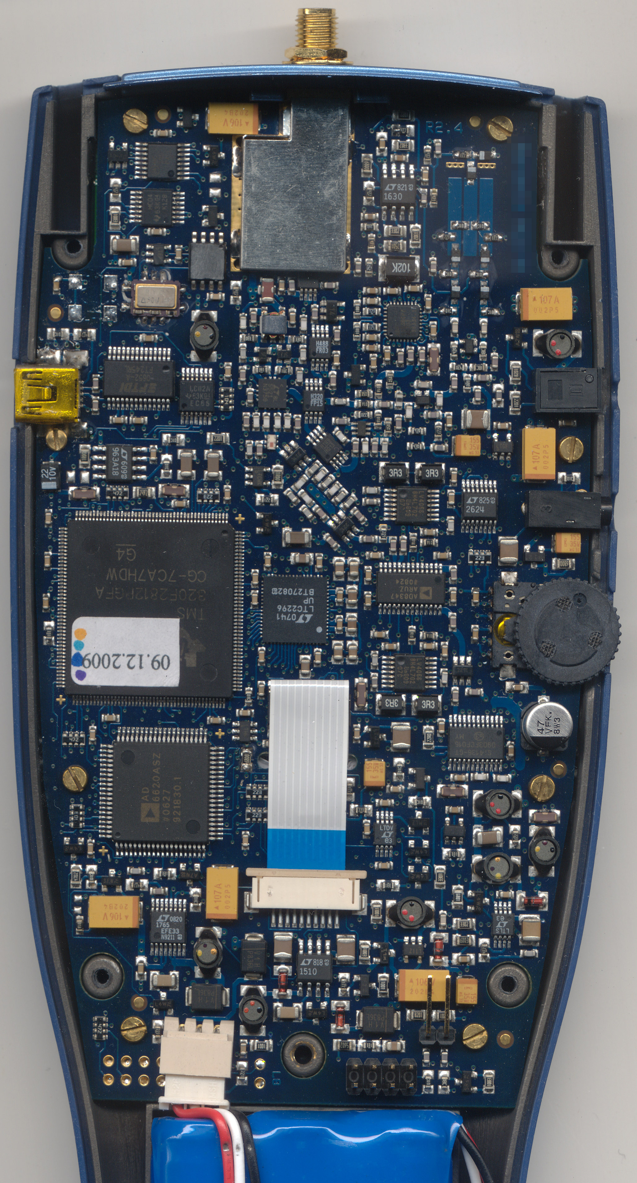
The Ware for February 2011 is shown below. Click on the image for a much larger version.

I was loathe to take this one apart, but finally curiosity got the better of me. Enjoy!
This entry was posted on Wednesday, March 9th, 2011 at 10:37 am and is filed under Hacking. You can follow any responses to this entry through the RSS 2.0 feed.
Both comments and pings are currently closed.
I’m going with this: http://www.directindustry.com/prod/aaronia-ag/handheld-rf-and-microwave-network-analyzers-58710-391530.html
The external ports available are: some sort of RF, a volume control, a headphone(?) jack, an unknown (possibly barrel power?) jack, and a USB port. So something to do with RF and measuring things.
The frequency range of interest is suggested by the 25Msps LTC2296 ADC near the TMS320 SoC and an AD6620 67MHz digital receive signal processor, the latter which further specifies the function of the device.
So based on the blue paddle-shaped housing, it’s an Aaronia HF-4060 handheld spectrum analyzer, right?
I think the dual 14-bit ADC (LTC2296) means this is one the “Professional” models: HF-6060 v2.4?
-Noah
Looks like this one is done already, but an additional feature that hasn’t been pointed out are the slots bracketing the RF terminal for bearing the weight of the attached antenna assembly.
My reaction to this one is battling between pride (that I was able to narrow it down to a handheld RF spectrum analyzer based on the picture alone, I usually am pretty clueless about what the ware actually is, but enjoy reading the analyses) and wondering if you might have made this one a bit too easy. At the very least you probably should have cropped out the bit of (extremely distinctively coloured) casing that is showing. I don’t think I’ve ever seen that particular shade of blue before…
Wow, I think Jonathon nailed it; even the edge of the housing matches the Aaronia color scheme. Less than 45 minutes, even… impressive!
Aaronia has other models that fit the bill, but I bet the hardware is very similar if not identical.
Actually their Spec-A doesn’t appear to have the SMA on top… so I’d say HF-Detector 3 PRO A3. Regardless, I concede to Jonathon.
Yeah, it looks handheld from the shape of the housing and the battery (I note that the wires over the battery are a little pinched, too). I like the little filter/resonator built with SMD components and PCB traces at the upper right. I’m also amused that the maker bothered to shave off the chip at the lower left corner of the shielding near the SMA connector. The little network of components that are mounted diagonally is cute. Quirky board, that. Lots of nice LT and AD parts, so lots of RF analogue stuff going on. Brass screws, selective gold plating, and one of the screw holes looks to be in metal, not plastic. A surprising number of SMD ferrite inductors, too. The smarts of it would be the TI DSP chip. Looks like some sort of RF analyzer, expensive, moderate production run size. I don’t see power RF parts, so probably not a signal injector or TDR type device.
> I’m also amused that the maker bothered to shave off the chip at the lower left corner of the shielding near the SMA connector.
Do you mean the unmarked 8-pin IC, 4 legs per side?
Why was it shaved; just to keep its identity secret?
-Noah
That’s not selective gold plating, the whole board’s been finished with gold (you can see that the vias with thin soldermask have been plated a little). Where the solder has been re-flowed is no longer gold, that’s all. It’s a ROHS finish, but also has the advantage that when gold oxidizes (say, blank boards in not-so-controlled storage), it’s still conductive. It is suspected of leading to reliability issues though, I’ve heard of companies getting boards gold-plated, and then stripping the gold back off when they need to assemble units for hi-rel customers.
Hello
(very) low end spectrum analyzer
As a HF guy (or call it voodoo :), i have heard a lot of these…
The dynamic range is small, and ghost frequencies appear at some frequencies (they are then compensated in software, leaving holes). So much for the reputation…
It seems to employ a quite nice technique: modulate the LO, to compensate for the image (in the DSP), which is OK for avoiding expensive filters, but reduces performance a lot, as it is very limited by the dynamic of the ADC (14 bit in this case, ltc2296, which gives 84dB, but you need a lot of margin on that value)!
seems to be patented as DE000019530812C2
Also i suspect that this technique gives a lot of artifacts if a modulated signal is present at the image…
The IF is not shielded and lies close to high speed signals, bad.
older versions even had no shield on the input : http://www.bartels.de/oliver/messgeraete_innen.jpg this guarantees to give out all the digital crap of the board in the display.
The metal-painted housing ensures that there is not too much noise going from the PCB to the antenna which can be connected just outside, but the LCD itself probably spits out a nice spectrum, unshielded…
Conclusion : it’s quite OK for testing the output on a transmitter, but really you can’t trust it when dealing with multiple signals with different amplitude, such as measured typically in the air.
For the price, it’s much better to get an old “real” analyzer.
I have at home a HP140T, i got in a trash, and just changed a shorted cap in the power supply filter. After 35 years, this thing is still pretty precise !
http://www.sy-yq.com/HP/PIC/hp140t.jpg
Hello again
From the frequencies involved, i can say this is the HF4040 coz of the input mixer limited to 3,7GHz
Some components are a bit out of spec from their frequency limits…
Some annotations on the RF path :
http://f4eru.free.fr/NTW.pdf
1: interdigital filter with varicaps serving as variable resonant element for the oscillator
2: first oscillator (LO), using 1 as feedback
3: PLL circuit for the LO (IC =?)
4: analogic drive for the varicaps, probably higher voltage, could contain the wobulating part. lt1630 = fast rail2rail OP
5: lt5521 : first mixer
6: SPDT switch selecting either the out of 5 or an unknown signal (reference ? direct input ?)
7: two simple discrete LC filters (different IF frequency ? different BW ?)
8: SPDT switch for selecting the filter to use
9: AGC and second mixer (quadrature)
10: si4136, LO for 9, around 2,4GHz
11: Dual ADC (I and Q)
12: reference TCXO. Note that LO1 and LO2 have each separate quartz. Probably the micro just measures all the XTAL frequencies involved and compensates in SW. Some soldering on this area, the 4 pins left are probably for another form factor of the same
?: what are these 3 Hxxx components ? another one halfway under the shield. LO1 goes in the lowest one…
Under the shield : the preamp
Things to notice :
– this version doesn’t have a metallized housing !! very bad !
– even the first LO is not shielded, no comment…
– the battery wires have been pressed
Wheee, a fellow RF guy! Here are some notes to supplement yours (which I enjoyed):
Those HNNN parts are Hittite ones. From the bottom up, a frequency doubler (HMC189) with 4-8GHz output, an LNA (HMC320) spec’d for 5-6 GHz, and a mixer (HMC488) with RF spec’d as 4-7GHz, IF as DC-2.5 GHz. I’d bet the obscured chip is an amplifier for the RF signal. Too bad the IF just disappears, as far as we can see.
Is it likely/possible that the other input to the filters before the 8347 is just unconnected, so that they can switch out the end of the signal path when the system is (say) tuning, or adjusting its gain control? The filters themselves make me nervous, I’d be worried about the “switched out” filter causing impedance troubles for the “switched in” one, is this normal to do?
I’m going to bet that the two filters are for different IFs. if you take a look at the Si4136, the IF output (60-1000MHz) disappears into a via, but a mysterious [ground] patch shows up and traces from that via to the other input of the switch that leads to the 8347 input. The low end of the 8347 range is 800MHz.
In my own work, I’ve avoided vias in RF paths like the plague. This design seems to do it once in a while, any comments on the matter?
The PLL at (3) is a type of package Analog likes to use for their PLLs. The pin connections look sensible for the ADF4193, and the frequency’s in the right range. The only other 32-pin PLL chips are the 4150 (pre-release) and the 4350 (which has an integrated VCO, so would not use that RF oscillator at all).
I’m going to say its an Aaronia HF-4040. Its not the 2025E because the TI DSP has the 64k of storage, but its not the 4060 because that advertises to have 1mb optional storage and I see no 1mb storage chips or any unpopulated pads on the board. Interestingly enough, these things are the price of a car.
I had no idea this kind of device (portable) existed, so I wondered how much it cost.
Now I understand why bunnie was reluctant to take it apart.
I’m not quite sure where you get cars for under 600 euros, but do let me know. I could sell a lot of them in China. :-)
Mostly reluctant to take it apart not due to cost, but for fear of miscalibrating something — at multi-GHz frequencies even bending a cable too much can have an effect on performance. I need to have faith in my tools…but in this case you get what you pay for. It’s good enough for what I use it for (debugging EMC issues) but the performance is nowhere near the US$30k++ Agilent analyzers (now *those* are the price of a car…well, in the US. $30k doesn’t even cover the cap-and-trade tax on cars in Singapore).
And yes, dang, I should have cropped the housing. :P
I am a bit of a greenhorn, so I will take a stab at it. With that AD Digital Receive Signal Processor it’s probably a frequency analyzer for the GSM and/or CDMA type air services. Brand or model? No clue on that. :)
Ohh , looks like a Spectran.
i am also curious about the chip with its face ground off, makes sense when i saw this in a parallel port security dongle, but what is the purpose here?