The Ware for April 2011 is shown below, click on the image for a much larger version:

Enjoy!
This entry was posted on Sunday, May 8th, 2011 at 1:39 am and is filed under Hacking. You can follow any responses to this entry through the RSS 2.0 feed.
Both comments and pings are currently closed.
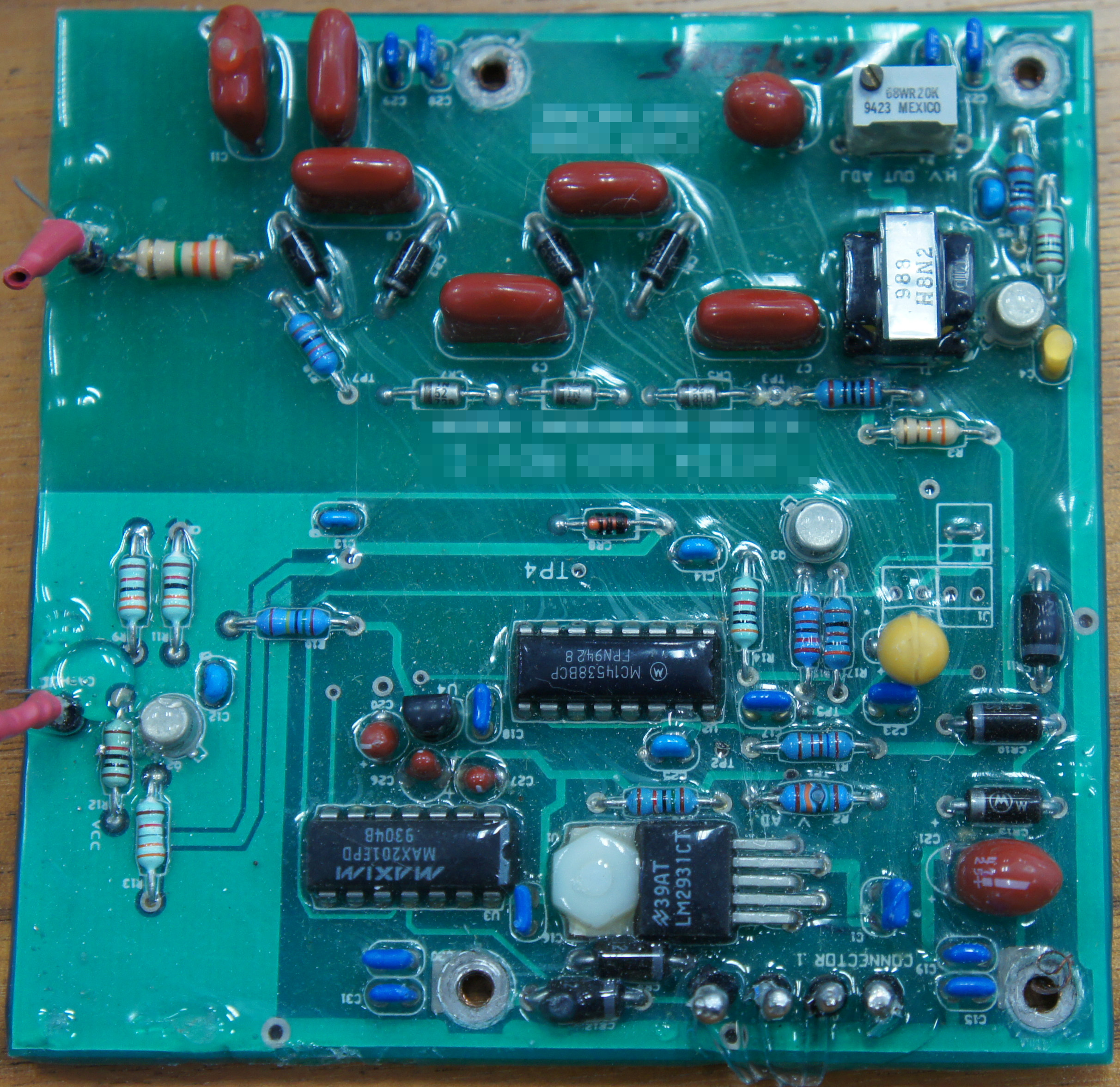
Perhaps the front end of a Geiger counter? Looks like it generates a high voltage for the tube along the top. Then amplifies the pulses, stretches them and converts then to RS232 levels along the bottom.
My guess for this name-that-ware is a geiger-counter frontend that is designed to feed pulses to a PCs RS232 serial port.
The upper circuit (with the transformer, red capacitors and diodes) for sure is a high voltage generator. It has a 3.3 MOhm resistor on the output, so the device attached to it for sure has to be high-impedance/low current.
The layout of Cs and Ds even maches the sketch on http://en.wikipedia.org/wiki/Cockcroft%E2%80%93Walton_generator
and it has a HV adjust potentiometer.
The magnitude of the voltage should be well above 100V, because otherwise you wouldn’t take the effort of the voltage multiplier and just generate it directly from a small transformer.
On the other hand, everything I’ve seen operating in the >3kV region had much better separation of low- and high-voltage parts than the layer of lacquer/epoxy applied to this PCB.
The geiger-counter tube sold at sparkfun.com lists 500V as a recommended operating voltage, and their recommended circuit has a 1MOhm resistor on the HV output line.
Also there is not much filtering on the output which rules out more delicate devices such as large-volume solid-state radiation detectors (i.e. Germanium detectors that also regularly run on >1kV bias supply).
What I consider the signal input (lower left) only has a few kOhm-range resistors and a single transistor (Q2, there’s also Q3 just in the middle of the board). So whatever the input signal, it doesn’t need a sophisticated, highly linear, or multi-stage amplifier.
This also matches the pulses from a geiger-tube (which has intrinsic amplification from the avalance of electrodes accellerated towards the center electrode, and are therefore quite strong) nicely.
There doesn’t seem to be a coupling capacitor in line with the signal input, so my guess is that the geiger tube is connected in series between HV out (which then has to be positive, matches the HV part) and signal input.
The remaining ICs are a linear voltage regulator, most likely to stabilize the power supplied to the circuit, a RS232 line driver and a dual monoflop.
My interpretation of these parts is, that the monoflop converts the very short pulses delivered by a geiger-tube to something in the order of a few microseconds, so that it will survive the low-pass filtering normally employed on serial port lines, to prevent glitches in data transmissions (typically 115k2 bit/sec -> 10usec bit width).
The RS232 line driver MAX201 will then output these pulses with +/- 10V levels (pin10 on the max is an output and goes to the leftmost connector on the lower side of the PCB). These signals then can be fed to the status-lines on a PCs RS232 serial port (DCD, CTS, RI) which will trigger a interrupt and allow the pulses to be registered.
The four pins on this connector most likely are (from left to right): Signal Out, ???, GND, Vcc.
The “???” pin might even go to the MAX201 and be converted to a control signal that allows to turn on/off the circuit, but this is even more guesswork than the rest.
There’s a string of three Zener-Diodes (CR5=1N5281B=190V, CR6=???,CR7=1N5273B) that most likely clamp the output voltage. That would make it 418V or 494V depending on if CR6 is the same type as CR7 or CR5.
why is it water proof?
Not waterproof, it’s potted, probably for the dielectric (there’s high voltage at the top).
You’ve got what looks like a standard Villard Cascade voltage multiplier (cap + 2 diodes at each stage) along the top, generating a high voltage output.
Also interesting: the low-quality/old conformal coating over the board.
The transformer circuit at the top right looks to be an inverter, to step up some DC voltage to a medium/high-voltage AC waveform for the voltage multiplier.
The main ICs are a dual monostable, and a RS232 level shifter. There doesn’t seem to be a microcontroller (it’s PTH and there are no pads resembling another through-hole IC on the back). I guess it generates a high voltage pulse when triggered over RS232. Or they might be (mis-)using the RS232 shifter as a robust board-to-board physical layer, comparatively immune to the massive noise/EMI that must come out of the HV section.
Conclusions: I have no idea what it does!
Whatever it is, it was probably made in ’94…
Interesting how the level-converter is wired; there is no apparent UART on the board, so I’d say this is just being used as a general purpose line driver.
Top-side U3 signals are pin11 (T1OUT) to “Connector 1”, pin7 (T2IN) I would guess is connected to the trace coming out the end of the the trigger chip, and a long trace is coming from J3.
The long trace from J3 to U3 is interesting; T2OUT would be a reasonable endpoint, but there seems to be a more direct path. If that is the case, my guess is that T1IN and T2IN are shorted, perhaps so the output signal also disarms the HV circuit.
Also, the terminals on the left appear to be marked Anode/Cathode.
For a specific guess, I’d say this could come from a GM-10 from Black Cat systems. It specs a serial port, which is consistent with the level converter, but user forums report that it actually outputs pulses.
Maybe (PC gadget )air ionizer (or negative ion generator) . UART as a simple source of AC signal needed for dc/dc converter.
Came here to say what has already been said.
The top is a 520V power supply (voltage calculated from 1N5281x2+1N5273), leading to a 3.3M resistor, to a lead marked “Anode”. This is clearly powering a Geiger tube.
The bottom is more curious, the MAX201 is connected to the 4 (cut) wires at the bottom (pin 11 T1OUT is clearly seen connected).
There’s a monostable. Whole thing is powered by a 13V regulator (15k + 150k).
So Geiger tube with the pulses being transmitted out by a Serial line.
R2 (above the leads of the LM2931) doesn’t look terribly happy.
I believe the coating is acting as a lens there.
[…] Name That Ware @ bunnie’s blog! Filed under: EE — by adafruit, posted May 10, 2011 at 12:00 am Comments (0) […]
Definitely Geiger Counter board. I have a very similar unit. Probably a Geiger Counter that is to be mounted stationary?
I looked at various radiation alarms, and they all seem to have more than just a speaker. So I’m going with neutron counting pulse module with RS232 outputs.
Something very similar to this:
http://quaestainstruments.com/docs/q.npm.2000.hv.Manual_9-10.pdf
But with fewer control signals, and about 15 years older.
Hi Russ,
the instrument you link to includes a spectroscopy amplifier and pulse-height analysis circuits. This neutron-counter most likely has a fast ADC after its charge-integrating main amplifier, followed by a FPGA for signal analysis and a microcontroller/CPU. Twenty years ago things like that were implemented in a multi-stage analog circuit (with pulse-shaping/bandwidth-restricting and thereby S/N improving filters), e.g. this module here: http://www.jlab.org/accel/inj_group/testcave/mott/590a.htm
For solid-state detectors, the lectures of Helmuth Spieler explain a lot of this (part IV): http://www-physics.lbl.gov/~spieler/Heidelberg_Notes/
This month’s name-that-ware’s circuit is much, much, much simpler.
Chris
I realize that, but the physical configuration would be similar, just without all the bells and whistles. The connector would only have power and an RS232 level pulse out.
sonar board for a some-kind of ROV
HEY! Its the 4th of June already. Where’s my Name That Ware May 2011 ?
:p
hello I love your site absolutely
Nice site you have here, I have a christian based forum where we all can talk about religion and come to know jesus christ.
I don’t think I’ve never read anything like this before. So nice to see an individual with some unique ideas on this subject. I really thank you for beginning it. This website is something that is wanted on the web, someone with a little originality.
I have the non-cloud edition for a while and it’s fine for general shared storage I’m using it for. The issue I find with it is that it does indeed randomly drop one of the HDDs. The drive simply does not wake up from sleep. I need to do a physical power cycle with the unit and it does a re-build (kept the original mirror setup as I don’t really need that much space. Had this 4 times since July 2010 when it was bought.
But the client could easily be updated (and the terms of service, too) to capture passwords, without informing anybody.