The Ware for January 2013 is shown below.
This is a ware I saw while doing the geektour of Shenzhen this past month. Try to guess what it makes! I will post a video of it in operation in the solution to the ware. It’s really fascinating to watch it run.
Automated connector making machine? http://www.freaklabs.org/index.php/Blog/MIT-Media-Lab-Shenzhen-2013/-MIT-Media-Lab-Shenzhen-2013-01-22-AUK-Connectors.html
Diaper making machine ;)
Aluminium parts (EMC shields, heatsinks) are fed into the machine, which cuts and place them on a board (on top of processor or RF components).
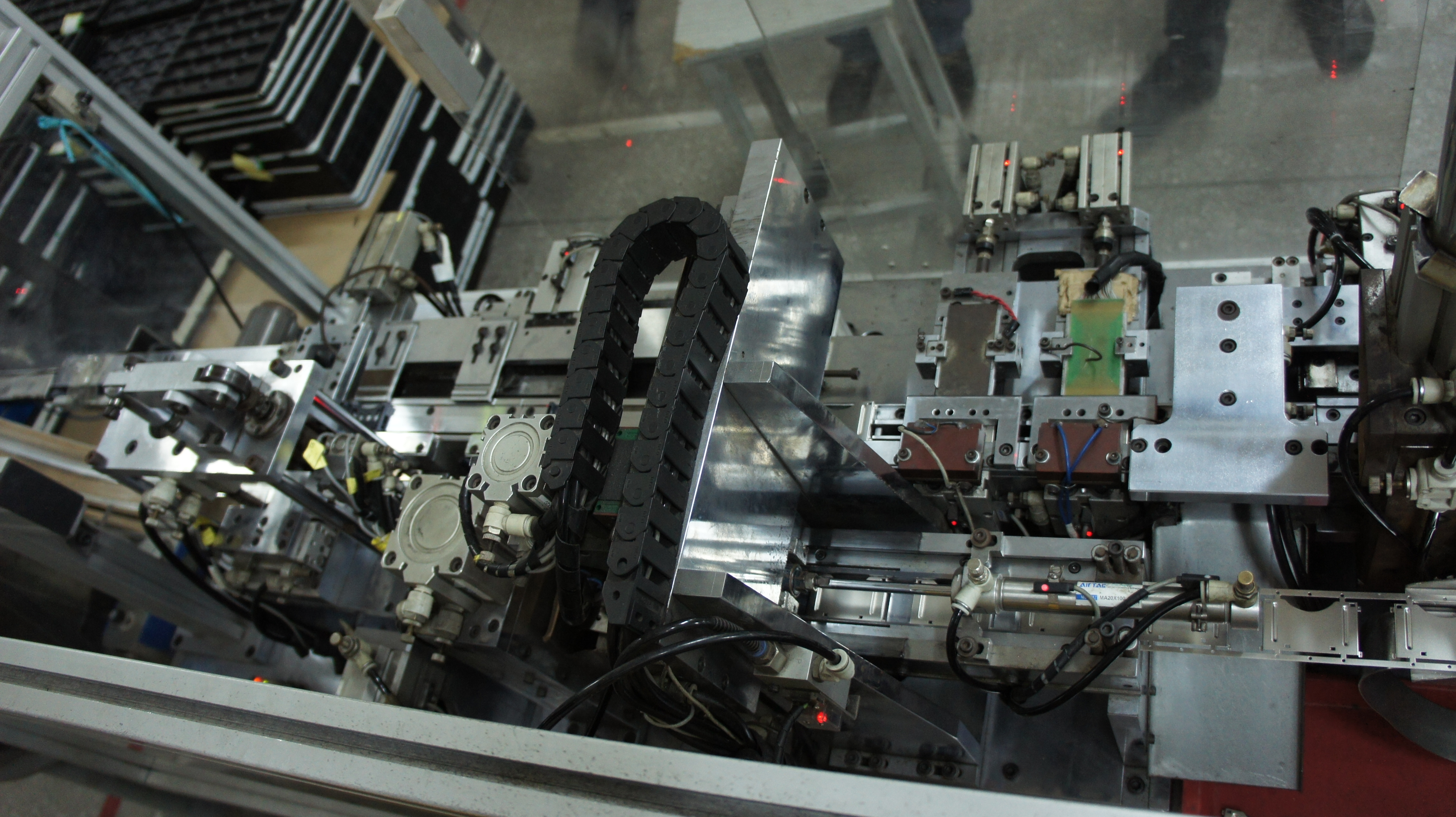
It have a protective plate and a small hydraulic jig. The size of the hydraulic indicate this will be a small part. The number of sensor and servo indicate this will be a very fast and small part operation.
I guess is the connection assembly jig. Perhaps even the USB or SIM card connector pin insertion.
The tray at the side also show that this is a small assembly line, and most probably automatic one.
The rail also show that the panel only move in a very small distance, and a few sensor above show that this is a very fine detail process.
I guessing this machine is part of the connector assembly line where by it was use to bend and insert the very tiny contact pin, etc USB/SIM/SD card connector.
Wow, lot of detail from Seba below:
From the specsheet he provide for AirTac, the AirTac 20×100 body should be around 176mm long… from the view, it seem that the metal housing is around 58mm long…and 35mm width. This fit the CF to PC card adaptor and the black plastic cover on left match it.
The whole assembly process seem like bending the metal piece into U shape and slot it into the black plastic piece.
I taking a wild guess, this is a China self made CF to PCMCIA card adaptor for Mercedes In car entertainment system.
It makes SD card readers.
It makes SD card sockets, you can see the top metal covers coming in from the right.
… though looking harder at the covers it might be making CF sockets in stead.
It could also be the other way round – feeding metal from the left … stamping and folding the metal cases for the card receptacle for an SD card socket… On the very left this could be a continuous piece of metal being fed in. However, the machine looks overly complicated if this were the only purpose!
On a closer look, I can see a second part of the metal housings (just right of the large aluminium bar), parallel to the parts on the bottom right. Looks like a more complicated socket with a top and bottom half that get combined in this machine. SD-card sockets however usually have just one metal part… I would exepect a PCMCIA socket to be longer…
Looks like the part is coming out the right side of the machine. And, assuming the rounded cut is about the size of a thumb, that would make this about the right size to hold an SD card, or atleast cover the SD slot.
Hm. Comparing the sizes of the other objects in the photo (feet, nuts and bolts, labels), I am pretty sure that this isn’t an SD card. Much too big. I would guess that it’s more like 5cm wide. PCMCIA would fit better, but I don’t think it’s that.
There are two rails. The metal part clearly feeds on the bottom rail from the right. The parts are still together on a single bar. In the top rail middle, you can see a single metal part, which the machine cut out of the bar I think.
On the top rail, left of the picture, you can see a part that appears to have a black plastic housing. I think that this is the final component, and that the plastic wraps the metal part.
I would guess that it’s a slot for some kine of cartridge. Some game maybe?
Looking at it again I am pretty sure it’s the connector housing for some kind of cartridge. Custom made I would say, probably for some gaming console – if they still use cartridges (I’ve got no clue about gaming consoles).
It looks like there are aligning laser dots all over the machine. Are those relevant?
They’re using pneumatic actuators, the red lights are the magnetic sensors that indicate the piston position inside the cylinder. One actuator has a visible label – Airtac MA20x100, control light confirms it’s extended. It’s datasheet is at http://www.airtac.hk/upload/201108171003377126.PDF, so it’s a double acting mini-cylinder, size between the thicker ends is around 130mm. They might not be using it’s full stroke. Comparing with the metallic parts below it we can estimate their length at around 50mm, width looks close to 25mm. The metal parts themselves look like the cover that is applied over the mainly plastic part which can be seen in the upper left corner.
The covers enter lower rail of the the machine from the right (as Arnuschky said), stamped into a steel ribbon. It looks like there’s a springed damper at the rail’s end to reduce reduce the ribbon’s deformation. The ribbon is pushed one cover at a time behind what looks like a buttressed support by the actuator mentioned above (you can see wear marks on the rail and lubricant spots around the actuated sled). In there a cover must be separated from the ribbon, transported to the upper rail and applied over the plastic part (the carrier was in motion when the picture was taken, again you can see wear marks from the flex conduit, behind the conduit you can glimpse the axis on which the carrier moves).
The plastic part enters through the upper left corner (you can see a chute where parts queue). They might be manually loaded from the trays we see. The plastic part then is loaded onto the upper rail and pushed to the right, where it meets the metallic cover. From there they travel to the right to two testing stations, where they are clamped by actuators from below and checked. The first test inserts what looks like a blank into the slot, maybe checking for a basic contact, the next test pushes in a PCB that has about 20 contacts soldered to a test cable. Each test has it’s own actuator (top right, fully closed in the pic), so they could be skipped if necessary. Note the coat-hanger that prevents the PCB from buckling :) The next station looks like a kicker that can discard a bad part down a chute and into the red bucket in the lower right. Continuing to the right is a much bigger cylinder – maybe it crimps the slot together more strongly.
The lower left part is trickier – we clearly see an actuator pushing on a lever that has a roller at the other end pushing down (looks like a valve rocker from an OHC combution engine). That multiplies the force and shortens the stroke, so perhaps it acts on a metal punch. We also see what looks like a ribbon with plated sections entering the rail from the left and a few other overhead and lateral cylinders. Probably a third component is created here and combined with the plastic part and cover, maybe some contacts, maybe an ejection or interlock spring.
Finally some words about the part that’s made. The cover has deeply embossed ridges that probably interlock with the card and it has cutouts for grabbing the card with the fingers which are mirrored in the plastic part. This means that it can be used with in a similarly shaped enclosure to allow the user to easily extract the card. This checks out with the images from the link posted by Hugo, pin count seems larger in these pics. Size is close to Compact Flash, but not quite the same, the ridges are clearly not CF, card interface is parallel (an older design?), pin count seems larger. My best guess so far is that the assembled product is a custom card slot.
I think it’s a cloned Gameboy Advance cartridge slot, sample pic http://upload.wikimedia.org/wikipedia/commons/8/8a/Game_Boy_Micro.jpg. LengthxWidth ratio, finger grab, 32 contacts – the match is pretty close.
A most interesting ware, one can almost see the operators tweaking and oiling the machine, adding the odd piece of wire to keep it running.
Many thanks Bunnie for writing this blog!
Without having any real conviction for why I thought this, the metal covers being fed into the machine reminded me of Nintendo DS slots. Searching the internet, I found the inside of a Nintendo DS which looks very similar.
http://farm1.static.flickr.com/14/90806787_7556143f47.jpg
Hi Bunnie;
I looked all over the site for a contact link.. not found.
Check this story – right up your Xbox alley?
http://www.slate.com/blogs/future_tense/2013/02/21/cell_phone_unlocking_petition_meets_100k_goal_white_house_to_weigh_in.html
p.