The Ware for February 2013 is shown below.
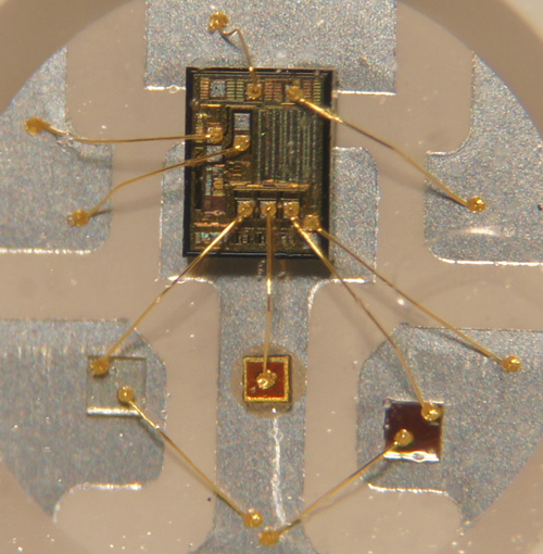
For what it’s worth, here is a close-up of part of the ware:
恭喜发财!
This entry was posted on Monday, February 11th, 2013 at 9:15 pm and is filed under Hacking. You can follow any responses to this entry through the RSS 2.0 feed.
Both comments and pings are currently closed.


Ummmm, seems like a smartcard pcb.
I’m not sure about the three smaller chips below – could be LEDs. So my guess is that this is a RGB led with a controller chip. I’ll go for a WS2801 RGB led module!
My guess is that this is an RGB led with built in drivers. The large die probably has PWM drivers and a serial interface.
Very interesting!
I’m confident in saying it’s not a (modern?!) smartcard IC as there is none of the characteristic mesh and anti-tamper on top metal. There are 3 additional small dies (?), two three terminal, one two terminal, of which only one appears to be on silicon. So an RGB LED sounds entirely plausible.
I’d guess it’s from one of those RGB LED ribbon/tape things (like http://adafruit.com/products/306 for example) – serially addressed pixels on FPC tape, encapsulated in some kind of transparent plastic. Not particularly high power (as is obvious from the lack of heat sinking).
The driver die is most likely a WS2811, since the pulse-time serial protocol only requires one signal in and one signal out, whereas WS2801 has both clock and data in and out, and there is not enough bond wires for that.
I think I’ve seen these around – Adafruit uses them for their new Flora Smart Neo Pixels. It’s a WS2811 die in a PLCC-6 LED package.
Apparently the actual part number for the LED + WS2811 is WS2812. Here’s a datasheet: http://www.nooelec.com/files/WS2812.pdf
Note the diagram with bond wires on page 2.
Nice! I’ve been looking for that datasheet for a while. :D
Oh no I didnt check my RSS feed last night or i have won the prize ;)
http://adafruit.com/products/1260
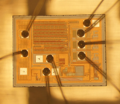
Before I found the datasheet I took a microscope shot to figure out the pinouts so its quite a flashback :D
That’s a great die photo – you can see the scan stitching between the ends of the flop rows in the std cells (note the extra tiny row flops snuck in to the left of the RGB output cells – I guess the extra pads are for scan (you can see the marks left by the probes)
I’m a bit mystified by the structure on the upper right – any ideas?
congrats for finding this! I’m always impressed by how you can come up with so precise and exact descriptions!
RGB led + driver all bonded in a 5050 led package
Nice stuff…