The Ware for November, 2005, is shown below. Click on the image for a much larger view.

While on my travels in Japan, I picked up a new camera, a Sony Cybershot T9 (japanese site / english preview). For the record, all of the photos on this website are shot with a Cybershot DSC-V1, a 5 megapixel camera with excellent optics and a night-shot feature.
I scored a Cybershot T9 at Akihabara on its Japanese introduction date (11/18/05); you can’t get it in the US until January 20th, 2006. The released model has only Japanese menus, so you have to be able to read Japanese to use it. The T9 is a 6-megapixel super-slim camera, also touting Carl Zeiss optics. Its best features are a very quick startup, rapid fire shots, portability, good battery life, and “Super Steady Shot”, Sony’s anti-shake DSP technology that allows you to take pictures in low light conditions and no flash and not have them be totally blurry. If you check out the blog entry below about Hong Kong and Japan, most of the Japan photos were taken with the T-9, and the Hong Kong photos with the V-1 (click on the links to see the photos, I use hyperlinks to save on bandwidth). The T-9 is a great camera for every day use, but I’ll have to say, I’m sticking with the old Cybershot DSC-V1 for the photos on this website. Despite its lower pixel count, the V-1’s superior optics (and I think superior image sensor/analog circuitry) yields crisper, more readable pictures.
For comparison, you can download the above hi-resolution photo taken by the T-9 with and without super steady shot enabled (you can see that super steady shot causes blurring of fine details, even though I have found it very effective in reducing macroscopic blur).
For those who prefer a side-by-side comparison, here is a small portion of each photo enlarged: left, 5-megapixel DSC-V1; middle, 6-megapixel DSC-T9; right, 6-megapixel DSC-T9 with steady shot turned on. The side by side comparison doesn’t highlight all of the flaws of the T-9, as the image quality varies with contrast, position on the image, and so forth, but it gives you a flavor for the situation.
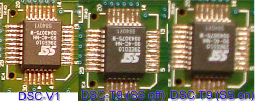
It just goes to show me that optics and sensors are as important, if not more important, than your megapixel count if you care about fine detail.
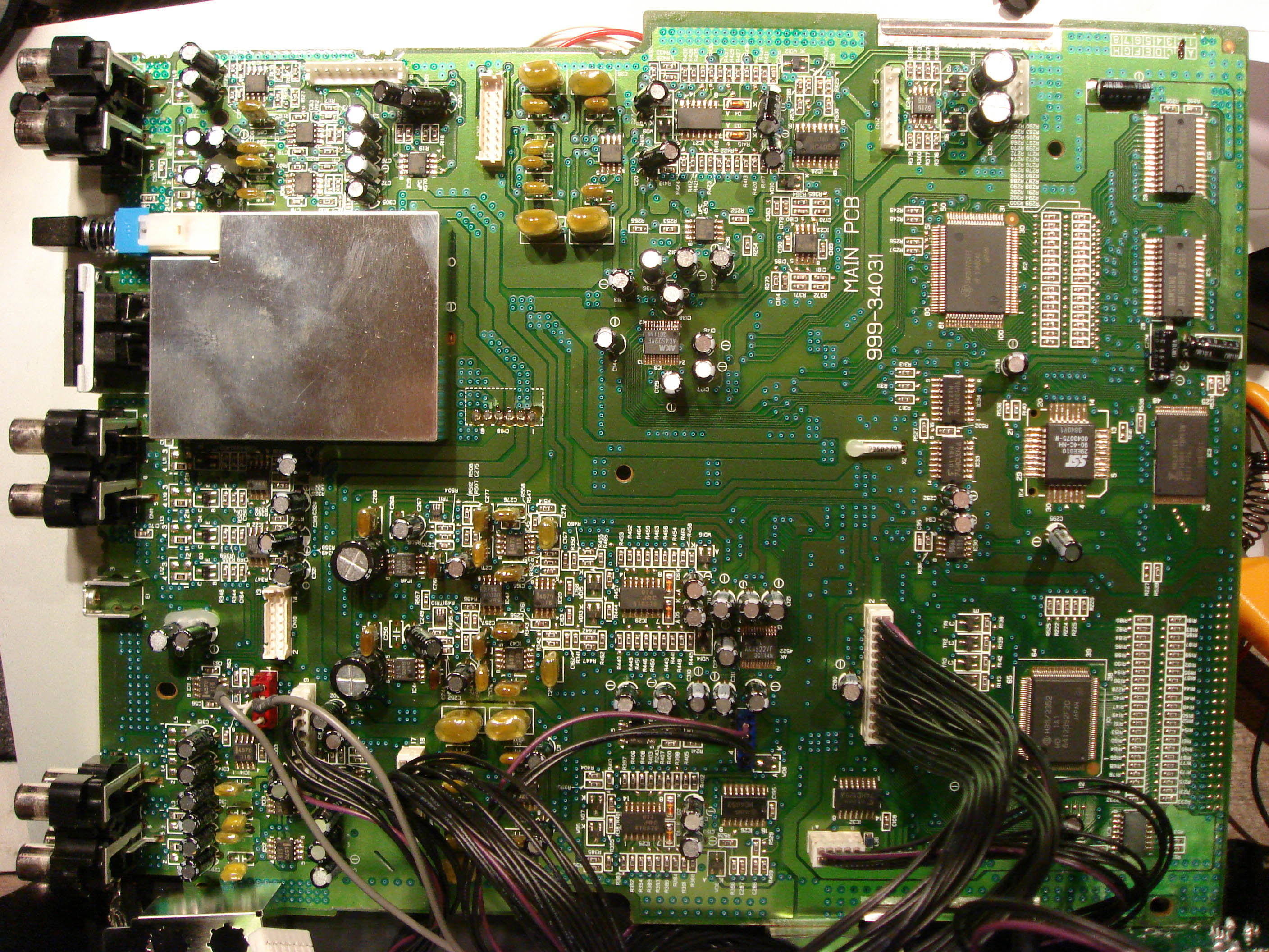
Nonsequiters about cameras aside, this month’s ware is a bit obscure, but I expect that someone will be able to guess it right out by the time the month is up. It’s a fun one, and I enjoyed taking it apart to see what was inside…I had been wondering what it looked like in there for a long time.
Cool Idea for a competition by the way, although slightly geeky…
The first thing that strikes me is the consumer electronics feel of the board. Cheap connectors all over the place. RCA connectors at the back etc…
In the upper right corner there is a signal processor (TMS…) with a RAM memory and 128K rom. Probably used for some kind of encoding/decoding… In the lower right corner there is another embedded processor 16/32 bit. Note the 40 pins on the right hand side of the board. Probably an ATA interface.
On the left hand side of the board there are 6 pairs of RCA connectors. Typical audio (or possibly video) input/output.
I can also see two stereo chains with an AD/DA (AK4522) at the end and the analog circuitry that goes with them. I also find an analog mux (4053). So the thing can obviously select between some audio sources or outputs as well as convert audio between the analog and digital domain.
I can also see the typical CD-rom audio connector coming in to the board. (Red connector on the lower left side).
The metallic box puzzles me. A metallic box usually means RF, but the connectors (5pin DIN) and the button on the box does not ring a bell in the RF domain, still I would guess on a FM receiver.
To sum up. Lots of audio in and out, a CD (or CD/RW) player, DSP and CPU with an ATA interface, possibly a hard disk as well. A radio receiver. I’m missing the audio PA though…
My guess is that this is some kind of receiver with a capability of playing CDs both normal and MP3 ones. Possibly with recording options as well.
/Olav
weeheee I can guess boards?
:D
What rules? Can I google the chips, or just the private Datasheet archive or .. ? Not reading the others comments either :D
– Back: 3 4blocks of Cinch connectors, one DIN/MIDI, a switch and a ground mount
– lots of analog audio stuff, AKM DAC chips, OpAmps and decoupling-Cs
– RF box besides the DIN -> DIN is combo AV output, the RF shieldbox is the modulator
– 2 flash roms
– Texas ASIC or MCU with 2 memory chips for the audio effects *g*
– Hitachi microcontroller (H8/2352, no ROM, 8KB RAM)
– the board is the main pcb, and not the entire system
-> We have a Texas DSP generating analog audio at the end, and we have a Hitachi CPU 20mhz with most of its I/O pins going for an IDE/ATA interface
I guess some “prosumer” audio equipment
No rules, really…you can use all tools at your disposal, google, datasheets, social engineering…the only key point is that if you happen to know the answer off-hand (e.g., you’re a tech who worked on a board like this or the likes) then a simple correct answer with no analysis (“it’s a foo.”) is likely to loose out against a well-reasoned but incorrect answer. It does get complicated, I guess, when people refer to other people’s posts, but if you do worry that you have the correct answer but you don’t have time to write it up, I will accept a sha-1 hash as a placeholder while you do more research:
$ echo “answer” | sha1sum
b33788c35f071c2873d8b1bb6d951a3f0c89bbed *-
Just post the sha1sum result and then give me the original string later on. sha1sum comes as part of the cygwin distribution, fwiw.
I have some doubts about the red connector being a CD audio connector; the standard pinout for those is L-gnd-gnd-R, whereas this one has two similar looking two-conductor cables coming out. Even if the audio channels were on separate cables (why?), the pinout would mean that they chose opposite grounding colors for the two otherwise identical cables.
Between the lower-two RCA assemblies is what appears to be a grounding screw attachment, suggesting mobile-mounted equipment.
The DIN5 suggests MIDI or a mic?, and the quads of RCA connectors suggest an audio mixer a la http://www.karaokemaniac.com/pioneerprodj/images/djm500rear.jpg
Current best guess here is one of those mobile DJ rigs with built-in CD player(s). But the pushbutton and RF cage are still throwing me for a loop.
I’m too frustrated to continue right now. will try again later.
PS: Hi Bunnie, long time no see. :-)
[pardon the hugeness of this post]
The AK4522VF stereo codec chip has two audio channels input and two output. The input lines are sampled and sent out the serial bus on SDTI.
At the same time, the data coming in on SDTO is DAC’d into a stereo pair of outgoing audio channels. Pin 13 (serial data out) on the upper AK4522 chip can be seen going into the TI signal processor, so we can assume that at least the input ADC on the AK4522 is being used, and that the TI is sometimes being used for processing input (this is not just a CD player). Pin 12 (serial data in) disappears into a via, but there is a likely candidate
connection just above that via which takes it also the TI signal processor, indicating that the TI is handling both input and output of audio. Thus, it seems likely that some of the RCA jacks on this board are audio inputs and some are audio outputs. The AK4522s are also intimately connected to the 74HC4040A 12-bit ripple counters, which are likely providing the clock signals to the stereo codecs, divided out from the base frequency of the small crystal located just to the left of the counters.
There are six RCA pairs, and each pair goes through a nearly identical analog front-end of decoupling capacitors and op-amps. However, there are some differences between the front-ends. The upper quad of RCA jacks and the lower quad seem to have identical analog front-ends, while the center quad is lacking some components. The large C-shaped layout of large yelow capacitors appears only twice and similar components do not appear to be associated with the central quad of RCA connectors. Also, there are only two AK4522 codecs and each can only handle 4 audio channels (2 in, 2 out). There is, however, a triple 2-channel bi-directional analog mux (HC4053) which could allow switching between the center quad and the lower quad of the audio channels.
I can’t figure out what the chip just above and to the left of “MAIN PCB” is, but it appears to be unique to the upper analog front-end. Also, the dual op-amp, pair of transistors, and large caps to the right of this IC are unique. This area of the board is still a mystery to me.
The quad AND gate and quad 3-state buffer in the lower-right look to me like they’re probably associated with something off-board. All of the visible IO lines from the H8S/2352 processor look like the either go to the ATA port (almost certainly a HDD or CDROM) or to off-board jumpers. A small number look like they might head off towards the signal processor and probably constitute a control and data bus. But based on the fat ground traces between the microcontroller in the lower right and the analog chains to its left, I think the processor deals with analog via the TI signal processor and not directly.
As an aside… the 10pin jumper in the lower-right, just below the quad 3-state buffer (74HC125A), looks just like the DVD power connector in my Xbox…
And of course, there’s the RF cage. I can’t think of a reason this would be here if it weren’t for something higher frequency than audio or MIDI, which makes me wonder if there’s some kind of video going in or out of that DIN connector. However, there doesn’t seem to be much around the RF cage that isn’t part of an audio front-end. There is one 6-pin off-board connector just to the right of the RF cage, but it looks like it is connected to a bunch of the big analog ground traces. Anyway, if there’s video in that cage I don’t think it’s really doing much. Maybe there’s a test-pattern generator in there? The switch… no idea there either. If it were a test pattern generator, the switch could just be an on-off toggle for it… but why? If there’s actually radio in there, why the DIN connector?
In conclusion, I can’t find anything that points to the ATA bus as being strictly input to the processor, so it could very well be a HDD. There are at least 2 stereo audio inputs and 2 stereo audio outputs. Two additional stereo audio lines are indeterminate but it seems likely that they are being switched out with another pair of stereo lines.
Best guess at this point (and likely my final guess, sorry for this huge braindump) is a sampling audio mixer/digitizer (I’m throwing up the white flag on the RF cage).
nipples
Mouser! Wow, nice to hear from you again. You still playing ultimate??
Great post, btw, love the detail!
Maybe the RF cage houses the powersupply? The connector next to it could look like power connector I think.
Still playing ultimate, though the season has more or less ground to a halt here in Los Alamos. Finally graduated back in May, am now working for the lab as a postdoc doing embedded system engineering, of all things. Course 22 wha?? :)
Flipflap is so right about the power supply. I can’t believe that didn’t occur to me. It explains the proximity of the analog ground fingers. And I even have a freakin mixer with a DIN5 power supply connector (some Alesis product). Though this is because the AC/DC converter sits in an external package. And if that were the case, you probably wouldn’t need the protective covering. So I’m still somewhat confused. But power supply sounds better than my goofy test pattern generator guess. Explains the button nicely too.
OK I’m off to work. Does this contest go on until someone correctly identifies the hardware?
Congrats on graduation! That’s awesome.
I typically let the contest run for one month, until I put the next ware up. A lot of good speculation happens, or at least people can learn from reading posts for the duration of the month. Your analysis is excellent tho, I think it will be hard to top it!
Bunnie,
You’re totally right about the DSC-V1 being a great camera for the money. I took a cruise a month ago and ended up buying a DSC-W5 since they don’t make a waterproof housing for the V1, and the picture quality of the W5 sucks compared to the V1 even though they have (allegedly) similar sensors.
It makes me wonder why someone would buy the W7 which has a higher resolution than the W5 but the same inferior optics.
This is a first shot for me at these contests, so I might be totally off-base here. :)
This sure does look like a DJ mixer to me. It would certainly explain the sets and pairings of the RCA jacks; deck 1/2 left/right at both phono and line level input, plus two sets of outputs (or something like that). The connection at the lower left side of the board just above the RCA connectors could be a ground, which is very common for things with phono preamps in them. The DJ mixer we have lying around the office (heh) is a Numark, and it has a Kaoss Pad on it for diddling in all kinds of crazy effects. Doing some googling brought me to a Korg KM-2 mixer, which sure does have a very similar rear footprint (as seen from the photo http://namm.harmony-central.com/WNAMM01/Content/Korg/PR/KM2.html ; just look at the rear jacks and overall size of this month’s PCB.)
That’s my guess, anyhow :-)
Look at the PDF version of the user’s manual, specifically page 3: http://www.korg.com/downloads/pdf/KM2_OM.pdf Look at that back panel.
We have a winner! ding ding ding…. ;)
Another pic: http://transmobil.fw.hu/kaoss_mixer_1.jpg
very nice thank you
beep phone
This is very different and the i know only the RAC connectors. Its there in the case in the left hand side. There are 6 RCA’s are there.
Please give the other things so that many people know about it. Really its a good post to know much info.
Does someone know when Resident Evil 5 for Xbox360 will be released?