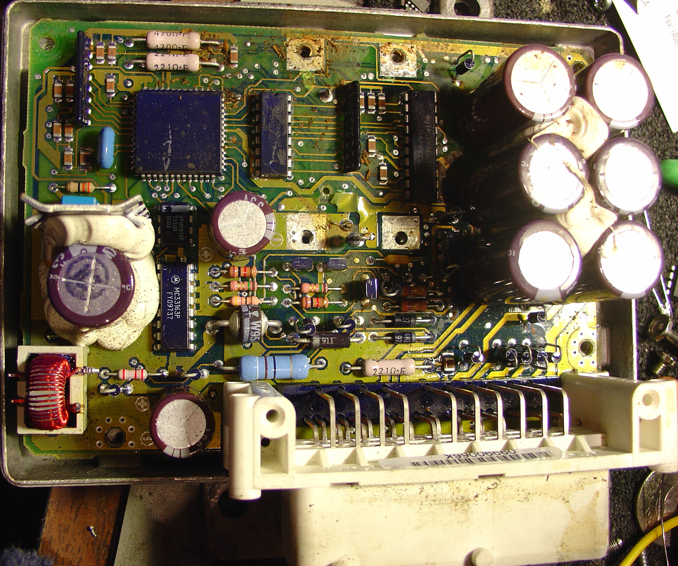
The Ware for January, 2006, is shown below. Click on the image for a much larger view.
This is the first time I’ve welcomed a guest ware into the contest. A friend at work (Mike Fitzmorris) handed me this unit and asked me to guess what this was, and suggested that perhaps I can put it up for the contest. To be honest, I couldn’t guess what it was off-hand (other than it was something used in a car), partially because one key part (a sensor) was removed to reveal the circuit board. So, I figured perhaps I could put it up this month and see if it doesn’t also stump a few other people as well!
January has been a hectic month (I got a probe station with a laser cutter!!!), and once again I am posting my ware at the last possible minute to still call it January’s ware. Let’s hope I don’t miss February outright! I have been able to find the time to make minor contributions to the Free60 project (see if you can’t guess which pages are mine…I’ve been posting under a different alias to avoid undue attention, as that can be harmful to good teamwork and make it difficult to receive honest peer review), and it has been very interesting to watch the progress of the project overall. Currently, it seems that the shader hack is still quite promising, as well as people looking directly at the DVD firmware. The quality and acumen of the hackers out there is simply outstanding. I don’t think you could raise enough money to form a company of finer and more motivated engineers–and remarkably, nobody is being paid to do this. I guess that’s the power of passion.
I’m going to guess a hot-wire mass airflow sensor.
I’m a software guy, so here’s my uneducated guess at what I’m seeing: a decent sized Moto part that is probably doing a bit of computation in the module, i.e. there’s analysis needed to convert sensor reading to something the car can use. A bunch of caps, so this thing uses up a fair amount of juice. There’s not a lot of pins to the sensor itself, implying the sensor gives a fairly simple output.
Off the top of my head, the hot-wire method is the only sensor I can think of that fits the bill.
Glad to see your contributing to free60. How do you feel about the new update breaking the kiosk disk.
I haven’t spent any time looking at the circuit yet… but wow that’s a gruesome trace lift there in the center… :)
Bunnie,
Can we get a better photo? At least one where the chip numbers are visible without needing fourteen levels of Photoshop filtering? :-)
OK, after some examination… this circuit is definitely… dirty.
With all the crud I’m having a hard time reading any of the IC part
numbers with the exception of two. First is the MC33163P. This is a “50kHz Multi-topology Burst-Mode Voltage-Mode Controller with 40V / 3A
Switch.” Looking at the layout, we can see that pins 12-15 are grounded which suggests that this part is configured as a step-up DC-DC converter. The example circuit in the datasheet indicates the use of an inductor, three capacitors, a handful of resistors, and a diode. The parts located around the 33163 correspond very closely to those layed out in the step-up example circuit in the datasheet. As it happens, this example is for bringing 12V up to 28V. This strengthens the argument that it is a car sensor interface, as the battery voltage would be ~12V and a lot of industrial sensors run at 28V.
The 8-pin DIP next to the step-up converter is the other part with a clear part number, but I can’t seem to find any reference to an “HM91AF.” Perhaps this is some variant of National’s LM91 (now obsolete) I2C remote temperature sensor? This would make sense in a circuit whose temperature was critical to its operation… like a hot-wire anemometer.
Unfortunately I can’t make out the complete part numbers on the Motorola processor, or the two Motorola chips to the right of the processor. It seems likely, however, that they are either a bus driver for output from the sensor to the car’s ECU, or some input conditioning from the sensor return.
If it is a hot wire anemometer, then the functionality is as follows: current flows through a very thin wire at a rate necessary to keep the wire at a constant temperature. As a fluid (e.g. air) flows over the wire, the convective cooling causes the sensor controller to increase the flow of current to the wire to maintain the temperature.
The 33163 certainly has the necessary guts to act as a fixed-voltage current controller with input from an external voltage source, such as the LM91. I’m going to put my money on this being the case. Therefore, the chips to the right of the processor are most likely bus handlers for the connection to the car’s computer.
I’m not sure what to make of the six big caps on the right… perhaps they are part of the input power conditioning, or some sort of protection circuit against the battery voltage drop when the starter motor is engaged.
ok
that’s one dirty board…
Known facts
came from an automobile
dirty(probebly works in the engine bay)
Had some kind of sensor (ONBOARD)
MC33163P is a switch mode/buck chip
One huge diode, I’d say >35A from experience
Sip resistors…common for logics…
6Lytics…humm….
From a Car eh?
how many sensors are there in a car?
MAP, MAF, OX, Temp, Pressures…
I could be a MAF, but I am not sure.
Looks too complicated for a MAF.
so many IOBuses…
making me dizzy…
Need to do some more research later…
This is an ignition controller, taken from a car.
Interestingly, all the chips are covered with a conformal coat which really interferes with the readability of the part numbers.
The part number for the QFP is SC422033CFM / 1025023 / 1993 TRW / 2C145QQAF9911
The part number of the chip to the right is MC74HC1051N / CPGC9907
To the right of that, next to the electrolytics, is MC145051P / QAF9906
The TO-92 enhanced packages are ZTX650 parts. And yes, the nasty lifted traces is where the sensor used to sit.
That should help out a little bit!
JimmyJo,
You also have to factor in that while the sensor is dirty, it doesn’t look cooked… so it’s not from the exhaust side. So you can scratch OX from the list of sensors.
Also the max sample rate of the A/D (thanks for the chip numbers Bunnie) is 20kHz, so we can assume that whatever it’s sampling changes at less than 10kHz. I’d also wondered in the back of my mind if this couldn’t be a chassis sensor for something like airbags, but it would seem a deacceleration sensor or yaw sensor would need higher fidelity than 10kHz.
I’m going to (perhaps foolishly) stick with my earlier guess: MAF sensor.
Thanks for the part numbers Bunnie… I can now safely recant my statement that the chips to the right comprise an output bus handler… :)
In fact, I can mostly strike everything I said other than “it is dirty.”
So I can’t think of any reason for a hot-wire anemometer to require a 11-channel ADC. There just aren’t that many voltages to measure. Whatever we have here, it’s either a MAF and something else, or not a MAF at all.
The ZTX650s and the MC33163P suggest high current at a voltage above 12V. The MC145051P suggests numerous return voltages to be sensed.
The HM91AF possibly suggests a remote temperature being measured.
Can’t find a refernce for a 74HC1051—could this be a 74HC105?
I’m intrigued by the amount of crud inside the enclosure. The fact that it’s there means that the enclosure can’t have been sealed all that well. This, combined with the fact that the sensor is mounted directly to the PCB, indicates to me that the module was meant to be installed in a reasonably benign environment (i.e. probably not the engine compartment?). Could this be part of the cabin temperature control system, like a thermostat or something?
Ah, it’s a 74HC4051, sorry. The left part of the 4 was filled in with the overcoat so it was hard to read. The microscope reveals all :)
As for the crud in the compartment, it looks like it’s dirt that had fallen into the box possibly after it was opened. There is some good dirt buildup on the white connector and its surroundings, and the dirt was probably retained when the box was removed from the car; when the seal was broken, much of the dirt probably fell in at that time. At least, that’s what it looks like from the pieces I was given.
Actually model# of the 8pin Dip is not HM91AF
That’s National’s date-code syntax
So you should search for something like LM7550/LMC7550 or something like that.
However, I cannot find any useful info reguarding what kind of chip it is…
And Bunny, are you sure its SC422033CFM, instead of SC422033CFN?
The tech from OnSemi said SC422033CFM is not valid,
and that SC422033CFN is some “Special Part”, and he won’t tell me anything more about it. lol
Is asking for Tech Support = Cheating?
This looks like an EEC IV engine control module out of a Ford car or light truck. Possible from another vechicle but still most like some kind of engine controller.
is that tobacco i see all over the board?
anyone thought of possiblity of heavy equipment use? I.E. backhoe? or possibly the cpu for the orginal atari 2600. Sorry, just talking nonsense. bored at work w nothing to do.
JimmyJo —
You’re right, it’s a SC422033CFN. The conformal coat has a bubble in it around the N, but under a microscope I can see now the difference between the bubble and the etched lettering.
Asking for tech support is not cheating per se, so long as you fess up to it :) Social engineering can be as useful a tool in the reverse engineer’s toolkit as any other.
Huh, a “special part”. They make it sound so 1337. :-P
Just a guess based on an real quick glance. Is it by chance the control module to an Allison transmission ?
This is what I got from OnSemi, HAHA
”
The device you are looking for is a special device and not from our standard catalog. It was created for a specific customer and we cannot disclose the datasheet or any information about this device since it is considered proprietary.
Sorry, we are not able to help you on this issue.
”
Simple sensor conections
Takes precise analog measurements(but not too fast)
8 channel multi/demulitplexer
2A NPN BJTs, 6 Lytics and a beefy diode.
The dirts looks more like its from the engine bay…
dirt inside the cabin will contain more fiber I guess*
Yellowish color… contain Fe3+?
the connector is not oil/waterproof
not cooked…
all these support the MFA theory
Maybe “Multi Element”
but why use like 30 lines for a simple MFA?
I seriously have no idea, one last line here.
“Pink does more than you think!”
I like the MFA idea as well, but why the 11-channel ADC?
I think this is the i/o part of an Electronic Fuel Injection System.
A 10 channel A/D for Air Temperature, Engine Coolant, Manifold Air Temperature, Barometric Pressure, Throttle Position, Battery Voltage.
None of which require would high sample rates.
would also fit nice with the MAF and MAP theories and explain why so many A/D channels.
I’d say it’s an ABS control module, that’s my official guess.
Other guess could be a stability control module, or active yaw controller.
Hail Bunnie!,
Long time listener, first time caller.
I proffer a joystick controller for a CAT earth mover, or similar construction vehicle.
Reasoning:
Produced by a company big enough to place orders for custom chips.
Time and effort given to provision of a stable reference voltage.
Multi-channel A/D, 6 caps fit nicely with spacial planes up/down, back/forward and left/right.
Hot melt glued components suggest designed for vibration, rugged environments.
The missing sensor worried me…, why would one have a sensor bolted to the module? The only possible reason would be to provide referenced spacial geometry. A CAT has a rotating cab, so ‘forward’ would require to change direction depending on which way the driver is facing. Likewsie ‘right’ and ‘left’ would change for steering the tracks.
The missing sensor could be some form of optical encoder that would determine referenced position and allow the transposition of the spacial planes.
As a general point, the module appears to be around 10 years old. Would a more modern design use LIN or CAN?
Many Regards,
17.
It’s for the door locks of a car. Looks alot like a Ford. Thanks.
Hi!
How are you?
its the SRS unit from a rover 800 1991>1996 I have an identical one in front of me the missing unit from the middle is an inertia unit code numbers are
2992a00104
S05410041
It’s a SAAB SRS (Supplementary Restraint System) Diagnostic Unit, Which checks the airbag status and operation