The Ware for March, 2006, is shown below. Click on the picture for a much larger view.
And you say, “but it is April”, and I say, alas, never fear. Although I am late, I am committed to putting up 12 wares a year, so this ware will run short. I already have my next couple of wares lined up for the shooting, so I just need the time to write them up (and judge them…that’s really the hardest part of it all, because the responses are always so good and detailed!).
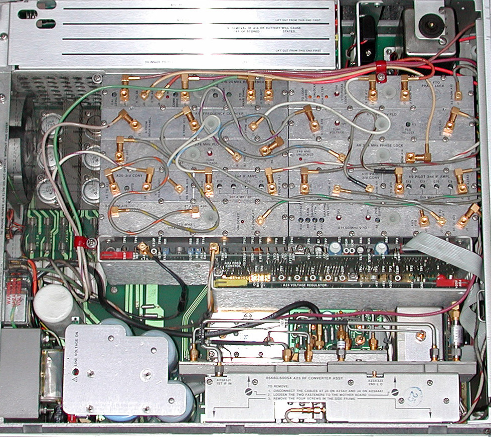
This ware is a write-in by John Miles. Thank you John! I love the way this one looks, such a wonderful mass of cables and RF waveguides.
Hmm, wasn’t that a bit easy?
The overall layout, the good descriptions tells me that this is either measurement equipment or very expensive “head end” stuff – really no consumer stuff.
the inscription & google tells me that this is made by 566e88f559fd91046eb73f8134dbd47f23bd16fa, and 3aae8203ed039a613407317865abcb78fb352a53 (that’s an url), page 6-6 shows the ware. sorry ;)
After all, it’s seems to be the RF frontend part of a e1fa83c70c69ceb92a83afc91baf7fc1cc07339b, namely the 1b137295e497459446a1a2cabb8a0577c0060fd8 (or maybe there are similiar devices?)
Sorry, i did not made any attempts to deduce what it’s doing. There are a lot of PLLs, frequency counters etc., so one could probably guess what it is, even without the inscriptions, but now, knowing what it is, it’s a bit boring as the PDF above has a good overview over the device…
Heh, I mostly submitted it because I was curious to see if it was considered “easy.” If most of bunnie’s readers are Xbox modders and other stereotypically-younger hacker types, then it would more likely be considered too obscure.
I see what you mean about one of the silkscreen labels giving too much of a hint, though. I overlooked it when I was trying to erase dead giveaways with the airbrush.
It is worth noting that if you merely Google the label in question, you will NOT arrive at precisely the right answer.
(Oh, it’s page 6-3, by the way, was a typo.)
Don’t worry, it was still a cool thing to see, and that’s what this contest is mostly about (for me) – seeing hardware from the inside which otherwise nobody would let you touch or even take apart :)
There are far too less resources about hacking expensive equipment – for example, i’m still playing with the thoughts to hack a “cheap” (digital) oscilloscope to implement the measurement functions i’ll never get in the price range which i can ever afford. Not sure if this is really feasible, but it could be fun. (And hopefully no $3000 loss…)
But once you have a framework, you could easily add functions in a matter of hours which would cost a fortune otherwise.
I’ve been thinking about hacking a cheap digital oscope too. Something like a bank of AD9480’s with a very precise, low jitter timebase doing interleaved sampling could get you to the 1 Gsps range, which is somewhat interesting for debugging older motherboards and so forth (as a reference, the 300 MHz Tek 3032B DPO runs at 2.5 Gsps). I suppose with a deconvolution filter on the back end you could push the sampling rate even higher…the analog bandwidth on the AD9480 is 750 MHz, but I presume that with some DSP and knowledge of sample history you can remove the “tails” of previous samples.
Could be a fun project. Wish I had the time to do it :(
I suck at hardware, especially at RF. So i merely thought of a software approach. My TDS2024 (no DPO :/ ) seems to run with an 68000-core (don’t know what processor exactly), plus that ASIC which does all the data processing including displaying them.. The firmware is upgradable via the CF addon, unfortunately I haven’t found any firmware upgrade yet for that model.
It has a service mode where one can peek/poke memory, but only with the frontpanel knobs – doing a memory dump or even modifying the memory wouldn’t be any fun, even if one would interface the knobs. If I have some more time, i’ll probably see if there’s any flashrom to dump and/or replace.
Sure, one couldn’t do any miracles (like DPO or something), but something like an I2C or UART analyzer would be all I want (for the beginning).
Or building an ethernet (/wlan) interface, adding external DSPs for advanced signal processing or something like this.
This appears to be a microwave frequency counter that locks
input frequency to a two much lower local frequencies that can
be directly measured. RF-converter is a fast sampling head, like
the ones in old sampling oscilloscopes. It uses 276MHz input to
produce series of very sharp pulses, probably using step recovery
diodes and transmission lines, and then uses a diode bridge
to cut very short portions of the input coincident with the pulses.
Thus the output is an IF that is a beat between input and the
closest harmonic of the LO.
One local oscillator (PILOT FLO ?) is harmonic locked to the
input, the other FLO is locked to the first with a small fixed
frequency offset. Ratio of (IF1-IF2) to the offset is measured
by the same low frequency counter that measures FLO with
respect to time base (top module and the oven in the right top corner),
and gives the multiplier to deduce the input microwave frequency.
Hewlett-Packard used to produce counters based on this
principle. Considering the quality of this apparatus and the fact
that now they cost very little, that is probably what you have.
For the interested ones, here’s the link to the pdf which has a drawing of the ware:
http://stgwww.home.agilent.com/upload/cmc_upload/All/08568-90118.pdf