The Ware for October, 2005, is shown below. Click on the image for a much larger view.
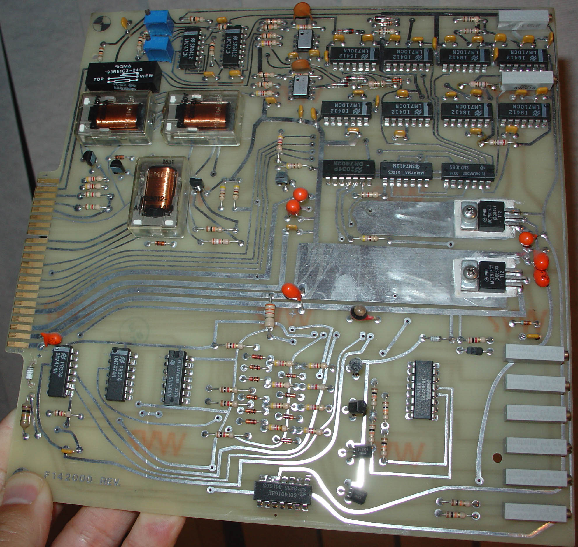
This month we’re going old school. I’m thinking this is probably one of the more obscure pieces of production hardware that I have sitting around in my house. To be honest, it took me some time to figure out what this thing does, but once I found the documentation on it, I was reminded that I take a lot of technology for granted these days. I’ll be impressed if anyone can name the exact piece of equipment this comes from, or if they can guess its precise function.
Some side notes–sorry the blog has been pretty quiet lately. Last month was brutal at work, I was putting in 100-hour weeks to get a chip out on time; fortunately, my new girlfriend is very understanding of my situation. I think that the hard work will pay off in the end. I’m now taking a little time now to catch up with friends and relax a bit before jumping back into the groove. I also got notice yesterday that one of my paper submissions to ISSCC was accepted, so I’ll be in San Francisco next February presenting a talk on a 10 Gbps integrated CMOS photonic system technology!
Another side note–you may have noticed the ads on the blog sidebar. The bandwidth overage charges from the comment-links in slashdot are starting to pile up, so I’m using Google’s adsense service to help cover the costs. I think the ads are fairly tasteful and inconspicuous (although poorly targetted due to the dynamic content generation infrastructure of this blog software); if they cause problems for anybody let me know. I don’t want these things interfering with the quality of this website.
I live in Spain, i have some boards from an old (60-70s) Rotary Telephone Exchanges from Telefonica that look a lot like this board (type of traces, use of mechanical relays, etc).
I wanna say it is some kind of to analog digital converter…
Well, on the upper-right, there are 8 voltage comperators, which i guess, with the NAND and OR gates (thermometer->binary?), form either 2x 2bit or 1x 3bit (flash-)ADC. There are four (almost) equally-routed lines, which end near on of the gates, and edge interface – could this be the result of a 2x2bit AD conversion?
The silver-painted ICs could be opamps or optocoupler, protecting the ADC from input glitches?
There’re 12V and 5V supply voltage, 12V probably used to power the relais.
On the bottom, there is again some digital logic (FFs, NAND-Gate), and two analog switches, one of them (the intersil) seems to have symmetrical supply.
Could this be a DAC, forming a fixed function generator? Could this be a carrier generation, used (with the ADCs) for demodulating something, then switching some loads based on the result? Honestly, i have no idea, and will probably laugh when i see the correct solution lateron.
This clearly comes from a time where fine-tuning boards to make them work was no problem. I don’t think it was produced in huge quantities (lots of space on the PCB, no brand markings), so yes, this might be (old) telecommunication stuff.
Hi. This morning i readed Microsoft Xbox Case from Andrew Huang,
so i come there and see this crazy SMART blog about identify ware…
I’m not expert, i see only a bounch of recistances, some voltage mos, some capacitors… AND A LITTLE SYMBOL IN THE CORNER that reminds me
Crash Test Dummies…
So i guess: this is the telecomunication board that is used in crash tests!
sorry for my menatal desease and hope you appreciate the humor..
Have a nice day!
This isn’t a filter-integrator-oscillator PCB for an old horizontal balancer, is it? From the ’70s or ’80s?
What is with that cap below the big area silver trace? It looks like it used to be the same orange color as the rest of the caps in that area, but it smoked/melted/overheated?
Looks like an LED to me…but what do I know, I’m a software weenie.
New girlfriend?!?! Won’t say more since don’t want to muck up the contest, but you’d better be prepared to give details next month. ;)
Old-skool caps were sometimes color-coded, instead of silkscreened with a numerical value. That cap is a 0.001uF device, I believe, part of an R-C delay element.
Good guesses everyone, but so far none are too close. Yes, the system is old; from the date stamps on the parts, you can guess it was built in the mid-80’s (I was probably playing video games on my Apple ][ and listening to Information Society or INXS when they were building this); no, it’s not a telecommunications device. Yes, it is from a production device, but it was probably not produced in any large volumes–I’d guess at most a few hundred were made. But, it’s something I’ve always wanted to play with and now I have one. :)
And Karin, you are such a troublemaker sometimes ;-)
Could it be that piece of @%*# [editted: please refrain from explicatives in posts] I threw out last month?
This particular board looks like it’s supposed to plug into a backplane. 44 pins was a pretty common arrangement in this time period, so it’s probably a proprietary system. Note that nearly all the trim pots face forward, probably so the user could adjust them without having to remove the board.
I don’t really think this was an A/D converter–by that time, prices were starting to fall on simple 4-bit A/D converter ICs. It looks more like the comparators were used to sense levels of things, and to trip logic that could be controlling those relays. Maybe temperature sensors, limit switches, or something similar.
The relays with the clear cases are probably DPDT, and the single relay above is obviously SPDT. Most of their connections appear to go to the edge connector, so they probably turn on heavier loads, possibly fans or even small motors.
Looking at the bottom of the board, the ICL5027 is a quad analog switch. The control inputs of it appear to be controlled by transistors, which are connected to the resistors and diodes to the left. It’s hard to see, but the connections to the resistors and the diodes goes to the edge connector on the other side of the board. This is probably a protection network for the control inputs to the analog switch. The switch itself is connected to the trimmers, which may well be connected as voltage dividers. I would imagine they set thresholds used by the comparators at the top of the board.
I have a feeling most of the interesting stuff is happening on the other side of the board…
This board just reeks of some industrial control application, although I’ve seen similar boards in scientific equipment as well. It’s a fascinating example of a board that has been taped out by hand on mylar.
Hmm. Eight analog comparators, four relays, a few latches, a couple of opamps (probably), and some generic TTL glue. LOTS of trimpots.
Nice glass-epoxy PCB, but use of 5% carbon film resistors (which were not considered especially high-class parts in those days) tells me it wasn’t from a top-tier manufacturer. Not HP/Tektronix-class.
I’d guess some sort of line interface card from a PBX, but what PBX manufacturer wants to ship a calibration nightmare like this board?
It seems to be designed to perform analog comparisons with levels established by the trimpots, and store or latch the results. The analog signal(s) are going to have to come in through the edge connector, because there aren’t any other visible ports for them. One guess would be a supply overload/overvoltage protection subassembly for a much larger system, perhaps a DEC mini.
Could also be some sort of analog-driven state machine. Maybe it’s a sequencing board from a copier?
OMG that’s the missing board from Oceanic flight 815 from Sydney to Los Angeles. Now it’s “LOST” at sea somewhere.
=)
First things I noticed were the six trimpots in the lower right, and the four relays, three similar ones and one other. Hmmm, three dimensions of control? The trimpots could set limits. Your comment that you always wanted to play with one might have spurred this guess: A controller for one of those arcade games where you try to grab a stuffed animal (in a bin full of them) with the crane?
Looks like a piece of a pac man or other video game system. Maybe another arcade style game…
could it be the motherboard for the new Xbox 360?
:D
Looks like some sort of DA conversion device, espesially with the gates, relays and regulated voltage. 8 pots for 8 bits? Maybe from old-skool printer? Printhead driver?
Is this from a Peavey Amplifier…Maybe a Profex?
Buy Propecia all you need to know about buy propecia
Hello! Good Site! Thanks you! vvhuyosqkbnkba
5def090cc3e391984f0b52ef7327a24b…
5def090cc3e391984f0b52ef7327a24b…
I just found your blog on the google search engine and saw a few of your other posts that you had done . I just added you to my Google News Reader. Keep up the great work. i will Look forward to reading more from you again.