The Ware for December 2012 is shown below.


If you’re seeing this, these are the backup images in case the caching server falls over. Most browsers won’t render these, but it looks like your browser isn’t supporting the hidden div tag correctly!
This beautiful ware was scanned and uploaded to me by an anonymous reader, who wishes to release the photos into the public domain. The boards are all from the same device. I love these boards, there is a lot of craft & TLC in them. Thank you for sharing them with us!
This entry was posted on Friday, December 14th, 2012 at 4:22 pm and is filed under Hacking. You can follow any responses to this entry through the RSS 2.0 feed.
Both comments and pings are currently closed.


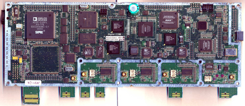
Some sort of Digital storage oscilloscope?
RF power amps? Microwave-looking voodoo? 4 high speed IF DACS… Lots of shielding… but also a lot of digital / DSP. Appears to have 3 similar channels, plus a faster one.
Anaren is a communications company. This gizmo doesn’t appear to have any receivers though. The RJ11 connector seems to have RS-232 on it. Date codes put it late 2000 early 2001.
Must be some kind of multi-band SDR transmitter. I’m going to guess from some kind of digital mobile phone network. Maybe CDMA, one of the power amp modules was designed for this.
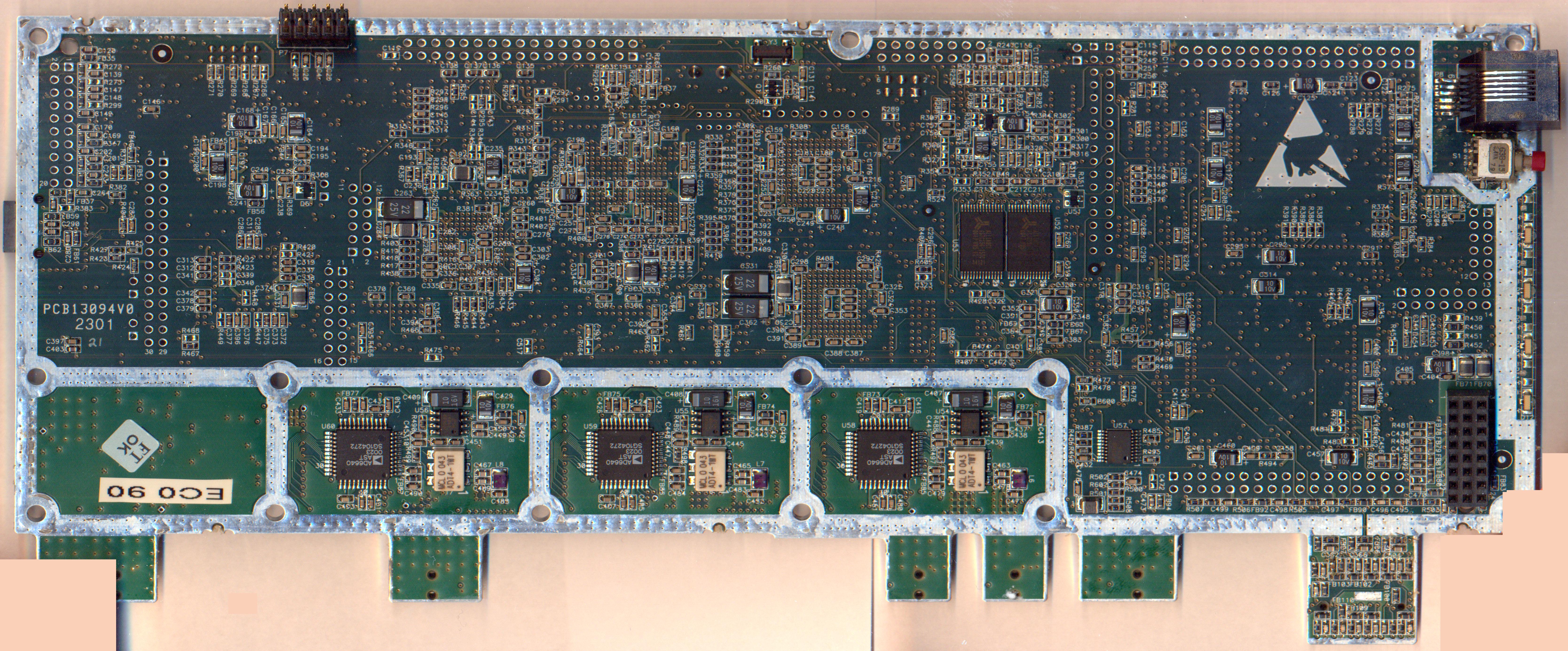
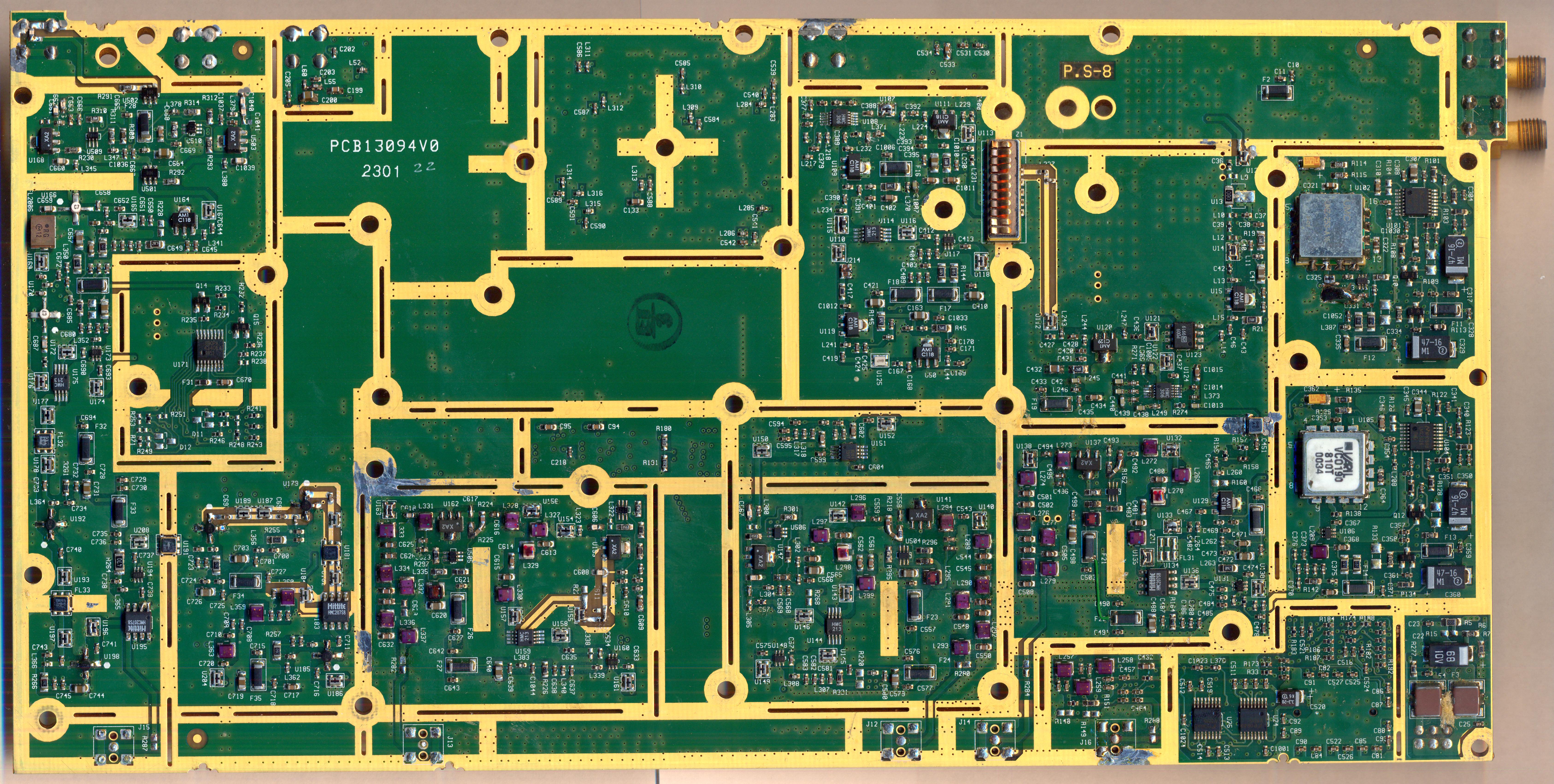
It’s got receivers, see the AD6640 chips on the bottom of ntw_dec_2012_digib.jpg?
Doh, for some reason when I looked those up I saw D/A not A/D.
I counted six antenna connectors in the second-to-last pic. That, combined with the ton of solder in the prior pic makes me think some kind of backward-ass transceiver, some sort of RF test hardware, either high-power output or just a short-run/custom part (the one with heaps of solder) maybe?
Gonna throw this out there at random: a cellphone network signal tester? Measures propagation, quality, interference, etc etc. With that much silicon, it sure is smart.
Some sort of ATSC transmitter prototype?
The clues:
1. Anaren 4ATTA0306 3-way splitter/combiner. Freq. range is 1.8-2.2 GHz.
2. MPT1923 vector attenuator: 1.94-2.34 GHz
3. The filter structures on the RF board seem about right for the 1.9 GHz band
4. UMZ253 VCO: 2.3-2.8 GHz
5. VCO190-810T VCO: 810 MHz These two combined is the first/second conversion.
Given that the baseband digital processing board included FPGAs, DSPs and special-purpose signal processing ASICs, I’d almost have guessed it’s a military radio system. There’s that RJ11 connector on the side, with an ADM202 RS232 transceiver behind it. Could it be a modem of some kind? It’s clearly a user-facing connector, since there’s also a push-button switch. A cellphone basestation module would have some other type of connector for high bandwidth I/O.
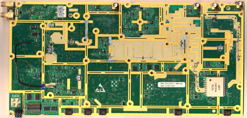
I feel kinda bad about this, but in the third photo, on the lower left in the copper there is the text “Wavesat”. Wavesat is a now defunct WiMax networking company. I’d guess that they built the assembly because it seems that those boards are made specifically for the housing, while the Anaren boards are not.
To add more detail; it appears the digital board (pictures one and two) sits on top of the RF board (the last two pictures). Note the board to board connectors in the lower portion of pictures one and four.
I’m gonna order my comments by what I saw first, so it may be a little strange.
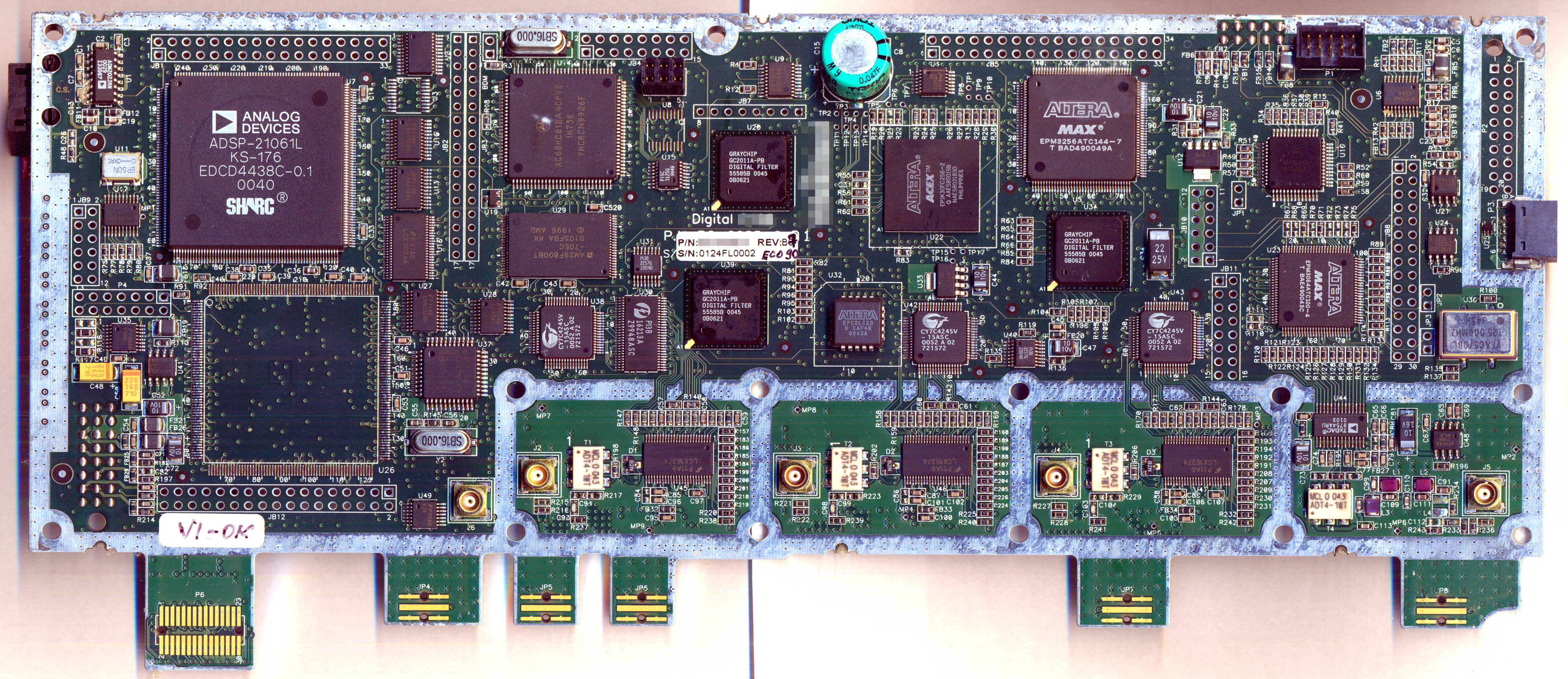
On the digital board, in picture one, on the far left is a baseband transmit section driven by an ADI 9754 14 bit 100MS/s TxDAC. There are three baseband receive sections each serviced by their own ADI AD6640 12 bit 65MS/s ADC which is buffered by a Cypress FIFO. PI3B 16213A is some kind of bus controller? for the ADCs. The white ceramic parts in each of those sections are minicircuits RF transformers probably acting as BALUNs.
Strange digital design, high end FPGA, some CPLDs, lots of fast 74x series logic, a Motorola 68HC! Graychip digital filters – which are really interesting, but would be done in a FPGA these days.
Ok, on to the RF boards (pictures 4 and 5). Starting in picture four, on the upper left are two receive connectors. I say receive because they are connected to what looks like a RF switch, then to a mixer, HMC213. The LO for this first conversion is located in the module just below the two SMA connectors. In picture five, the large silver can is the first mixer VCO, the SSOP is the PLL. Below that is the second downconversion LO constructed from a VCO190-810T and similar SSOP PLL. The second mixer (I think) is on the bottom, a HMC207S8.
The vector attenuator section with the MPT1923 is connected to the transmitter with the TxDAC.
Oof, gotta run, will be back with more / better notes.
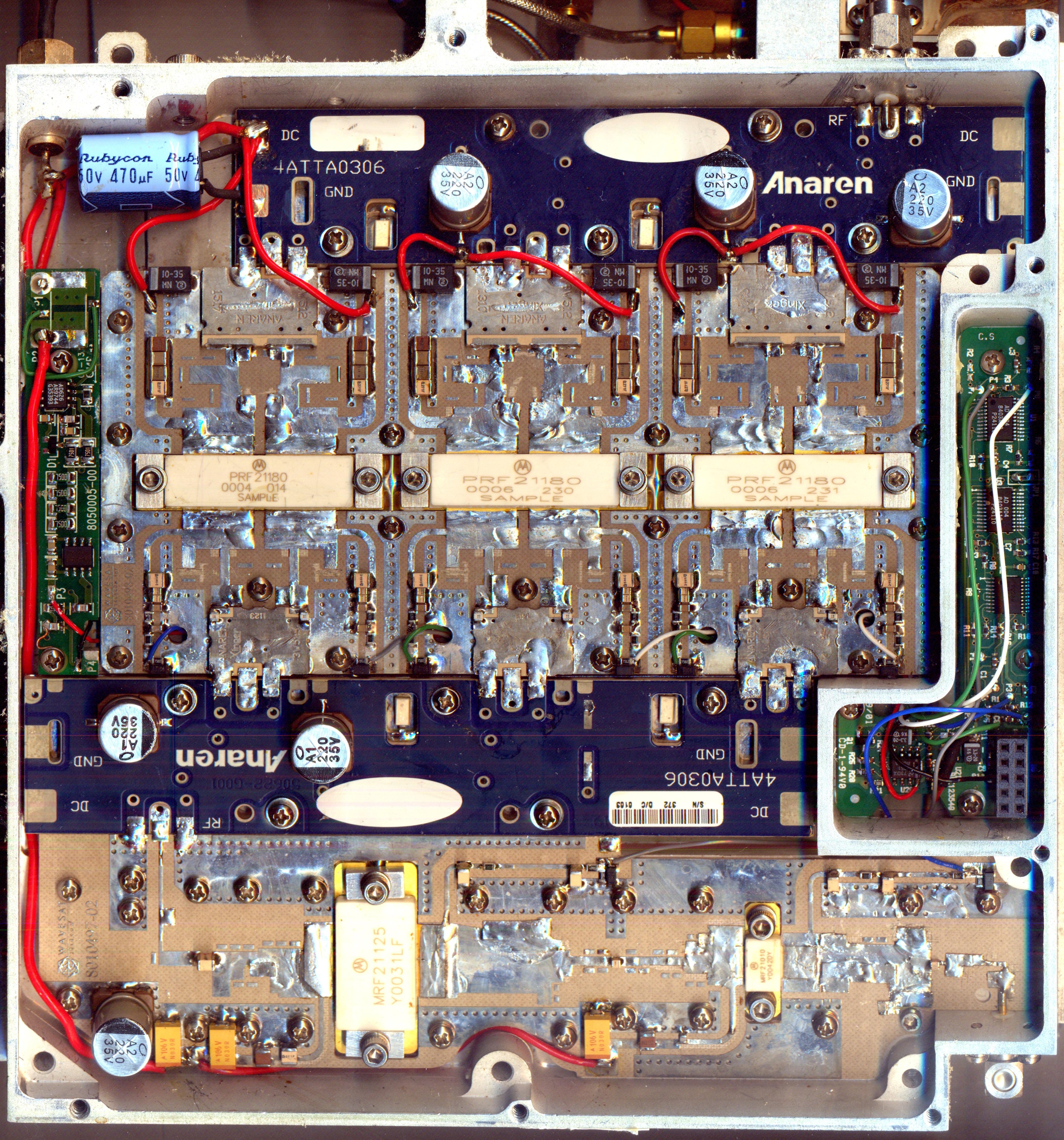
Real quick, that PA board is super interesting – Motorola parts marked “Sample” huh.
So here’s my theory, RF enters from SMA connector on bottom right. Gets first 10W of amplification from the MRF21010 then 125W from the MRF21125.
The Anaren 4ATTA0306 (blue boards) is a 1.8-2.2GHz splitter/combiner with “high power handling”.
Gets split three ways in the first Anaren splitter. The silver Anaren 3W512 are baluns for the amps.
PRF21180 does not exist, but MRF21180 does (Motorola RF FETs have MRF prefix – possibly a different designator for sample parts?). From the datasheet 21180 is used for 170W from 2110 to 2170 Mhz (narrow! and supports BW of ~3.8MHz) . It’s got two fets in a package for building AB amps.
Then, the same Anaren 3W512 baluns drive another 3 way Anaren 4ATTA0306 splitter combiner, the antenna is connected to the SMA connector in the top left.
I’d guess the other boards are powersupply and bias stuff, nothing major. I see a few op-amps etc.
Don’t feel bad, the original equipment this is a part of is not by Wavesat. ;)
Good :) didn’t want to spoil the fun
The hidden div images show up in the RSS feed.
Thanks, that’s a good note. it’s ugly, but I think i’d rather remember where to put dangling links than to make the RSS feeds look pretty.
This looks like a satellite transponder. Bent pipe maybe?
The large MRF21125 power FET near the bottom appears to be internally matched for the 2170 MHz band. That more or less confirms that this is a W-CDMA
The large MRF21125 power FET near the bottom appears to be internally matched for the 2170 MHz band. This more or less confirms that this is a W-CDMA base station, as suggested by Keenan. Using those transistors at any other frequency is a pain in the neck, if it can be done at all.
This looks like a repeater/booster to me, I cant tell the difference between GSM/CDMA just by looking at it.
The bulky outer case appears to be capable of withstanding the outdoor elements (or even a sledge-hammer).
So, with “mobile base station” pretty solid by now, the 3 chains were probably attached to a 120° sector antenna each, as is commonly done to get nice all-around coverage while retaining some selectivity.
Satellite phone base station?
The PCB# of the digital board indicates that this could be a part from a Tadiran product. Tadiran built military tactical radio equipment and also parts for aircrafts. I would exclude both, because of the types of connectors used. But it still could be something which Tadiran Telecom/Telecommunications (now ECI Telecom) manufactured.Wireless Link Transmitter?
Does the RJ jack link to a PBX? ;)
I would guess its showing boards from a CDMA Basestation, maybe even a prototype of it.
Upon further examination, a piece of an Innowave/Alvarion MGW system looks like a pretty good fit.
Whether you refer to it as WLL, MMDS, and/or BRS is another matter.
It’s pretty clearly prototype, maybe hand built. What makes it interesting or important enough for someone to release the images into the public domain? Probably the work of an engineer.
I really can’t comment on the relationship between these companies.
Tadiran ECI Innowave Alvarion?
I don’t know about you but it looks suspiciously similar in appearance to what is pictured here:
http://shop.bizsyscon.com/innowave-fau-1i-1-9ghz-multigain-wireless-86270919000/
Circa 2003
http://www.alvarion.com/addons/support/ics/product_support_form/MGW%20System%20Manual.pdf
Page 1-28
and the beginning of Chapter 4 is looking even closer
Most of that doc isn’t that interesting
One of those SMAs may take GPS in for timing/synchronization. Or it just goes to the RS232, instead or in addition to allowing for configuration.
It says that they can be ordered configured for the following bands
1.9 GHz Band 1.850 – 1.950 GHz
2.4 GHz Band Standard Version: 2.400 – 2.499 GHz
ETSI Version: 2.401 – 2.479 GHz
FCC Part 15 Version: 2.400 – 2.483 GHz
Allows for the reuse of some of the RF portions across multiple products
“ECI Telecom Innowave MultiGain Wireless”
InnoWave is a market-leading provider of fixed wireless wideband voice and data point-to-multipoint solutions. Its eMGW (enhanced MultiGain Wireless) product is a wireless DSL alternative access solution that operates in the 1.5GHz to 5.7GHz frequency bands. Its modular MultiGain Wireless (MGW) system uses field-proven Frequency Hopping CDMA technology to provide scalable toll quality voice, high-speed Voice Band Data (VBD), and ISDN-BRI services in the 800MHz – 3.8GHz frequency bands.
InnoWave Tadiran Telecommunications, Wireless Systems Ltd., a global leader in Fixed Wireless Access Systems and Wireless Local Loop solutions, offers InnoWave MultiGain Wireless Systems (MGW).
The BRS band uses microwave frequencies at 2.1 GHz and from 2.5 GHz to 2.7 GHz. Reception of BRS-delivered television and data signals is done with a rooftop microwave antenna. The antenna is attached to a down-converter or transceiver to receive and transmit the microwave signal and convert them to frequencies compatible with standard TV tuners (much like on satellite dishes where the signals are converted down to frequencies more compatible with standard TV coaxial cabling), some antennas use an integrated down-converter or transceiver.
Broadband Radio Service (BRS) formerly known as Multichannel Multipoint Distribution Service (MMDS), also known as Wireless Cable, is a wireless telecommunications technology, used for general-purpose broadband networking or, more commonly, as an alternative method of cable television programming reception.
It is most commonly used in sparsely populated rural areas, where laying cables is not economically viable, although some companies may also offer MMDS services in urban areas.
Just a quick bit explaining the relationship between the companies:
ECI Telecom and Tadiran Telecom merged in 1999. ECI’s subsidiary, InnoWave ECI Wireless Systems was sold to Alvarion in 2003. All of these are Israeli companies based in or around Tel Aviv.