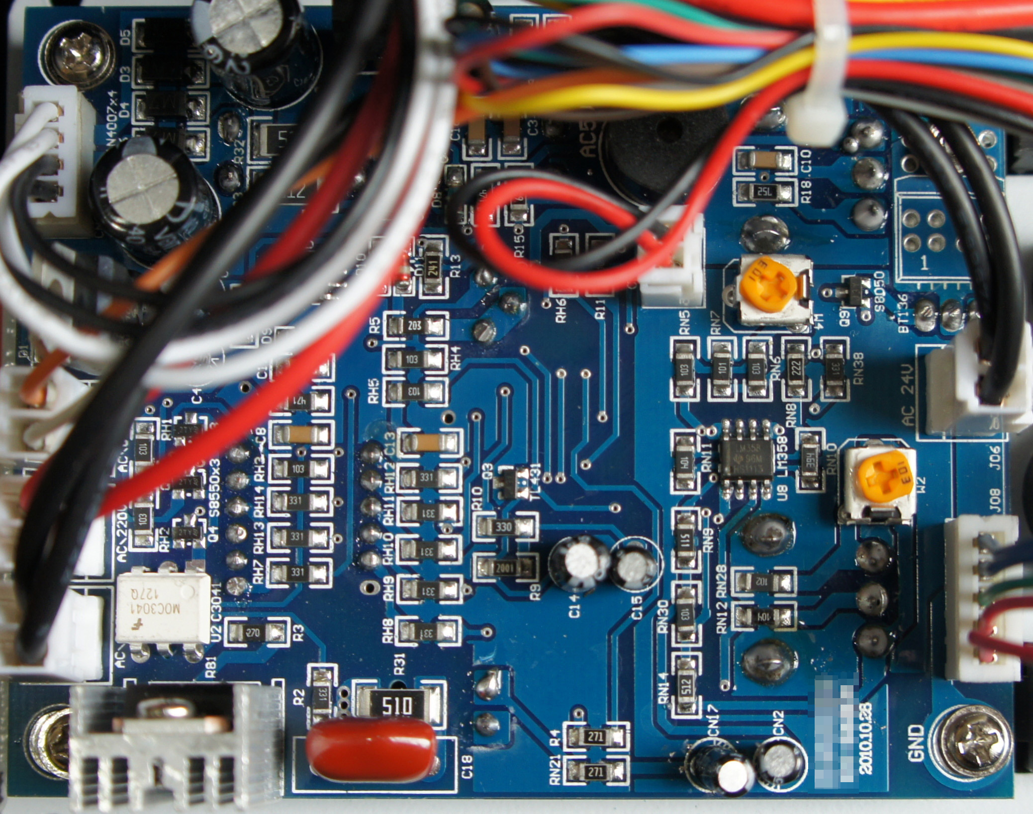
The Ware for March 2012 is shown below.

Been on the road in China this past month, so I snapped this one with my camera while on the go!
This entry was posted on Tuesday, March 27th, 2012 at 3:55 pm and is filed under Hacking. You can follow any responses to this entry through the RSS 2.0 feed.
Both comments and pings are currently closed.
Seems like a power supply to me
I see 240V AC and 24V AC I would guess that this is a power source for a door access controllers, electric releases, maglocks or CCTV as those are typical uses for 24V AC.
But the MOC3041 opto and the beeper makes me thinking of some kind of unintreruptible power source though there aren’t enough parts to support that – only if it’s a module of one.
Fan motor control power supply?
Yeah I also see the line voltage and also low voltage AC, and the beeper. Looks too “high tech” to be a power supply. I’m guessing the component with the heat sink is a triac, considering there’s only one and it is right next to a triac driver. So this thing is driving some kind of resistive load. There are power components on the back too (the 3+2 pin things) but not enough to form a full bridge, like you’d expect in an inverter or motor driver (or UPS, since a UPS needs an inverter). And the trimpots suggest a need for higher precision than I would expect from something like a lamp dimmer. There’s nothing digital on the board. And obviously it is part of a larger system what with all the chassis wiring about.
I’m going to go with guessing that it’s a temperature controller, for example in some kind of soldering equipment. Wild next guess is maybe it’s in a home appliance?
A voltage stabilizer ? The type with a transformer with multiple secondaries, one of which is selected to get the correct output voltage. So many pairs of mains wires would suggest that.
The circuit seems too simple for anything else, LM358 with two trimmers.
Something (Triac?) driven by a MOC3041, and another triac (BT136 marked on the silkscreen).
I’m going to go with some type of soldering station control board. Based on the number of wires and connectors, as well as some of te parts I see, I’m thinking a Hot air station, possibly a combo unit with a regular iron as well.
I can see at least 2 power semiconductor devices, one labeled BT136 on the backside and one on the middle left. The heatsinked device appears to actually be a power resistor based on the silk. Two board mounted pots can also be seen down the left side, based on the pins and mounting tabs protruding through the board.
The build quality is interesting, it looks like a double sided board, and the board is a full double-sided load since with a mix of SMD and PTH components. Typically the boards in the cheap import soldering stations are all through hole, and often single sided.
MegabytePhreak beat me to it — it’s definitely at least an analog soldering station, and most likely a combo hot air / soldering iron controller. Seeing the AC 24V connectors reminded me of the Open-Source Soldering Iron driver over at DangerousPrototypes (http://dangerousprototypes.com/forum/viewtopic.php?f=19&t=3475) — of course, this thing uses the LM358 Dual Op-Amp to do the temperature control instead of a PIC.
I count 4 AC connectors (marked AC\?, AC\220, AC\? on the left, and AC 24V on the right) — my first guess was that JO6 is the 24V output to the iron and the red/black cable in the center of the board is the tip temperature sensor, and the AC220V connector is the power input to the controller — but I see that there’s a 4-pin (black/white) connector in the upper left, which is connected to 4 diodes and some capacitors (so, a voltage rectifier to create DC for the temperature control circuit).
So, the black/white connector is the AC input, the black / black connectors are 2 heating elements, the red/black is a thermocouple, red/red and orange/white are mystery AC outputs (perhaps the blower motor for the air pump?), and the red/green/blue connector goes to a pot to adjust the temperature(s).
On that note, there’s only enough parts (the LM358’s 2 op-amps, the optocoupler, the red/black thermocouple) for one control circuit, so I don’t know what the other AC connectors are for. I *do* see a hidden 8-pin chip under the wires, maybe that’s another op-amp.
There’s a piezo buzzer near the top of the board which probably beeps when the iron is at proper temperature, or maybe if there’s a wiring problem?
It look like a power controller for a test device, like an osciloscope or an spectrum analyzer, or maybe for some high-end audio device!
Google search suggests 24AC is used in model railways, and there’s an obvious reason to have a beeper on such a power supply – shorted rails..
The other side seems to have 2 pots, a 3-digit seven segment LED display, a 2-pin device and a 3-pin device. Possibly a bench supply with voltage and current limit. The 2-pin part could be the overcurrent trip LED and the 3-pin one a current/voltage selector switch for the display. The 24AC is still puzzling, however. First thought is was a fan, but more likely the two-pin red and black connector in the middle is for the fan.
Spam, spam, spammity spam.