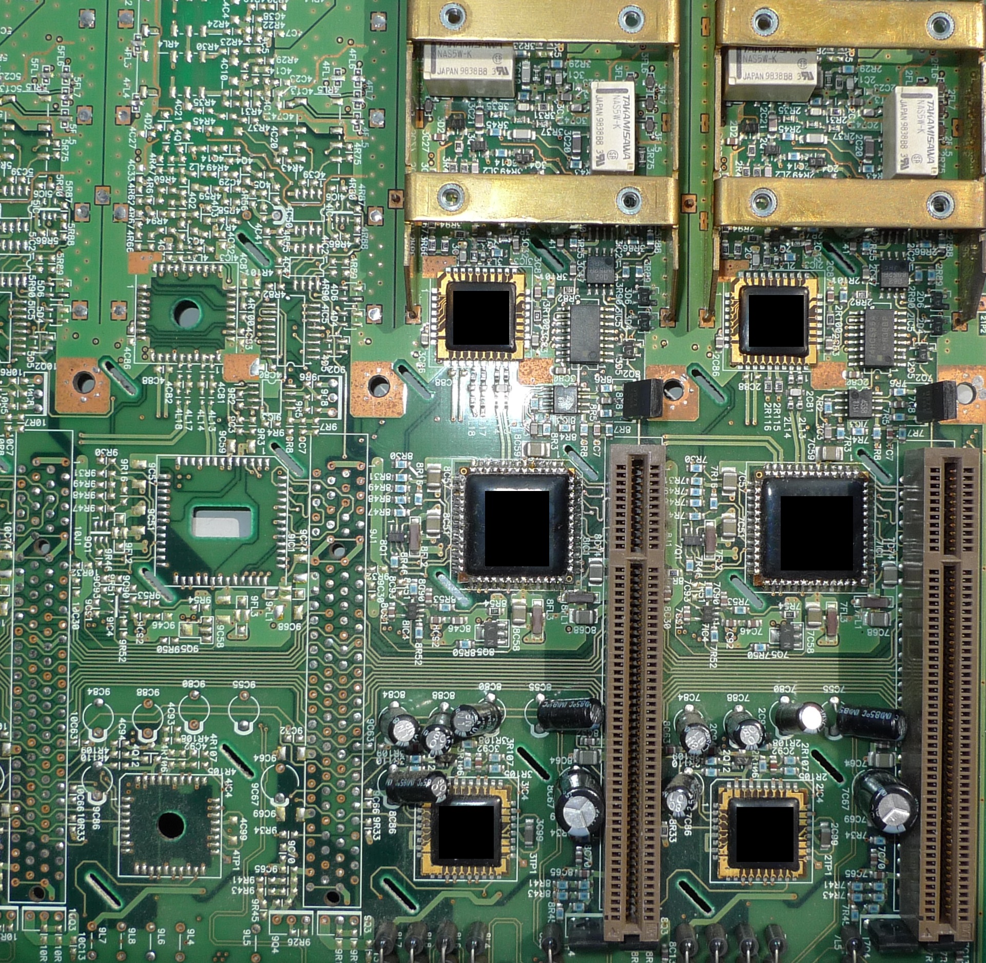
The Ware for October 2015 is shown below.
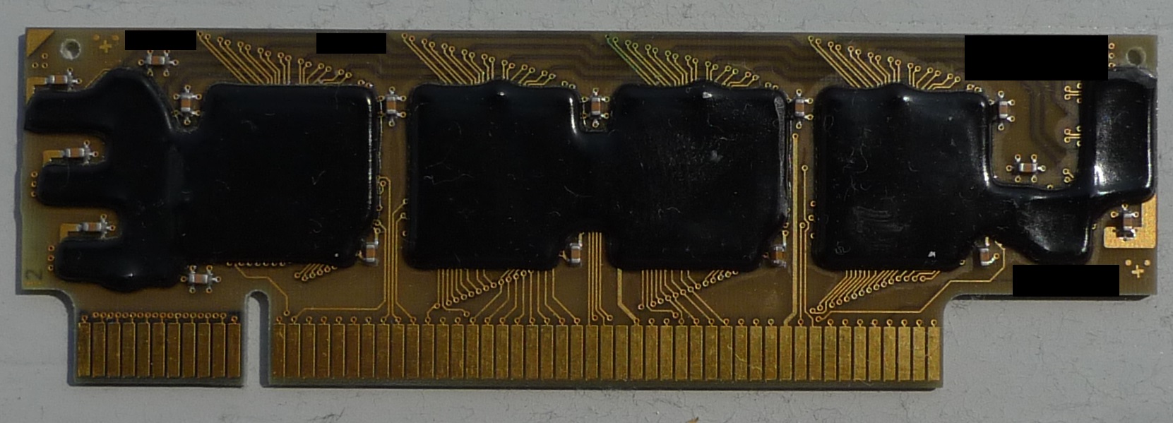
…and one of the things that plugs into the slots visible in the photo above as an extra hint…
Thanks again to Nava Whiteford for sharing this ware. Visit his blog and help him get permission from his wife to buy a SEM!
Seems like a digital sampling oscilloscope front end. The plugin is probably the sample memory. There are a number of differential signal lines going between the ASICs which would indicate a high-speed analog design.
Surely a 4-channel oscilloscope board with only 2 channels populated. The relays do AC/DC coupling, maybe ranging. The top ASICs probably do some ranging and drive the ADC ASICs in the middle. You can tell that those are the ADCs by looking at the unpopulated channel: there are a few (~8) traces going to the PCI-style connector, which as you noticed, are probably for the sample memory modules. Also, short differential traces between the driver and the ADC. I don’t know for sure what the ASICs in the bottom are, they look “quite analog”. I might guess they’re trigger generators. Anyway, the ASICs have distinct-looking packages, I’d guess a Tektronix of late 80s – early 90s vintage.
An interesting note: the holes underneath the unpopulated ASIC footprints. That’s where the cooling slugs go, for thermal transfer to heatsinks located on the other side of the board.
The large board appears to be the “main board” from a LeCroy LT342 Waverunner digital storage oscilloscope, or a similar model, from about 1999. Since we can see that all the channels are not populated they probably use it in several similar models.
Signal path is from the top down. Looking at the right most channel, the upper ASIC with the reference designator 2IC3 is an “HFE 428 1GHz Front End.” Next one down, labeled 7IC1 is an “HAD626 500 MS/S ADC” and the lower ASIC with designator 2IC4 is an “HTR420 Trigger Comparator”. The smaller board that plugs into the PCI type connector must be the sample memory since it is adjacent to the ADC. Oddly, I can’t find any schematic for the memory board in the LT342 service manual. The block diagram on page 11 shows four “Fast Memory” blocks connected to the ADC. Since I see no memory on the main board that must be the smaller board.
Service manual can be found at:
http://fablab.web-5.org/lib/exe/fetch.php/documentation:waverunner-lt342:waverunner-service-manual.pdf
The main board layout that matches the picture above is on page 191.
So razvan784 hit it right on by analyzing the layout. There is a mechanical drawing on page 159 that shows the heat sink mounting he mentioned.
Nortel switches used to use PCI connectores to hold groups of ASICs. Looked somewhat similar. Not aware that this was common…
As mentioned above, it screams oscilloscope front end and acquisition ASICs/memory (on small card) – I just couldn’t find the model like Carl did.
One note is that the memory slots appear to be using VLB connectors (from 486 era) rather than PCI – pin count and colour give it away.
… And VLB connectors were actually a re-use of connectors from the older MCA bus.
If anyone needs a cheap edge connector for use within a design btw, it’s always worth looking at PCI/PCIe connectors; they are used in enormous quantities and are thus extraordinarily cheap.
When I looked at the ware I purposely did not read the comments because I wanted to see if I could reason it out myself. I’ve seen Dave Jones of EEVBLOG and Shahriar of The Signal Path blog tear down enough oscilloscopes to recognize that the board layout was likely an oscilloscope. The area at the top with a couple relays and the metal brackets that look like a metal cover would screw on is typical of the input section, and the rest fit the usual digital layout. Then when I scrolled down and saw existing comments that agreed with that I wondered if I could figure out exactly which model.
The way I found the model was by the reference designators. Bunnie’s usual attempts to obscure important numbers that could identify the board wasn’t sufficient. :) I wondered if I could google them and find a schematic.
I’ve seen the style where parts are labeled with designators like 7IC1 when there are multiple instances of identical circuits on a board, where the leading number is the instance of the circuit, the the trailing number is the designator within the instance, and matches in each instance of the circuit. So it’s not like this method of designators is unique to this board.
But I figured maybe a combination of a couple of them would be unique. So I Googled “Schematic 7IC1 8IC1” and the third search result was the service manual for the LeCroy scope.
Wonderful detective work Carl!! & super quick – I had no chance this month!
Always a pleasure reading NTW, roll on December :)
Or even November it it comes first this year :)
I find it interesting that they started at 2 when they assigned designators to the front-end blocks. There is no 1IC3, for example, and 5IC3 is the ASIC for channel 4.
I guess they decided that 1IC3 might look too much like 11C3. If you made that mistake and paired the designator with the wrong footprint, could lead to interesting difficulties.
In Dave Jones’ teardown of a recent LeCroy WaveJet 354T, the scope had the same system of designators and the 1-prefix was used in channel 1. They actually seem to separate out into various blocks, not by board and not just for the channels, so that scope had designator prefixes counting all the way up to 14 or so across multiple boards (and there actually is a 1IC1 and an 11C12). Oddly, the main CPU board had no prefixes at all. So maybe the 1-prefix does exist on this ware too, just in another area or on another board.
The LeCroy in that EEVBlog video was actually designed by Iwatsu, and when I saw this photo that video was still fresh in my mind leading me to wonder if this was also an Iwatsu scope, what with the same designator prefix system, and the use of Takamisawa (now Fujitsu) relays in both. Looking at the model Carl identified, it appears it is indeed an Iwatsu (designed? or just manufactured?) scope, and was sold as an “Iwatsu-LeCroy” in some markets. I’m curious to see the ASICs/hybrids uncovered, are they branded LeCroy or did Iwatsu manufacture those too? Or are they third-party?
I am unable to find any information online about IC’s with part numbers HFE428, HAD626, and HTR420 anywhere but in LeCroy documentation. Of course, companies often have existing parts labeled with their own internal part numbers, so that doesn’t prove they are ASICs designed by LeCroy or Iwatsu, but in products such as this that is often the case.
The service manual states: “TV trigger uses a commercial chip (LM1881)”. So at least they find it an exception. Still no proof, but…