This month’s ware is shown below:
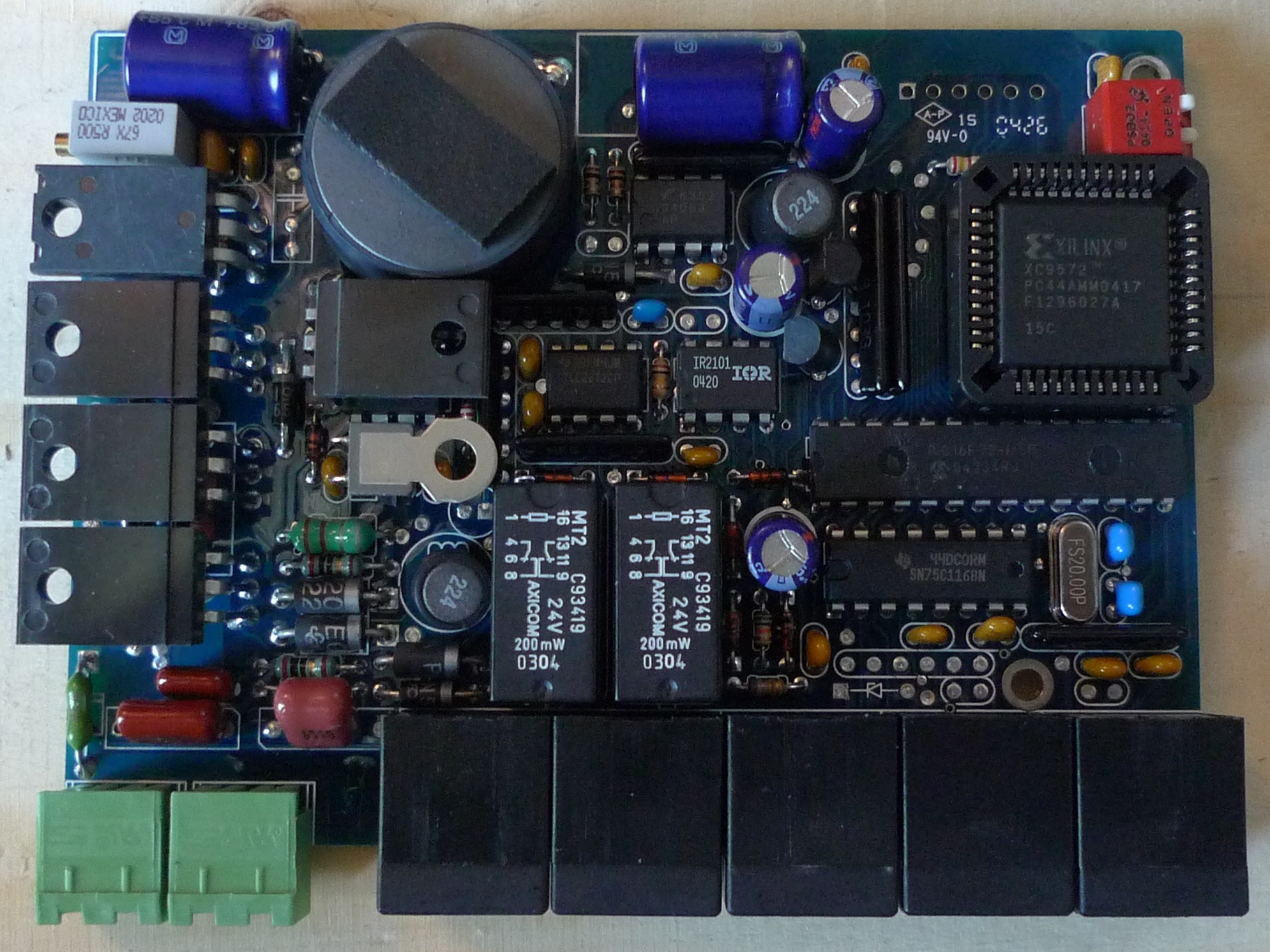
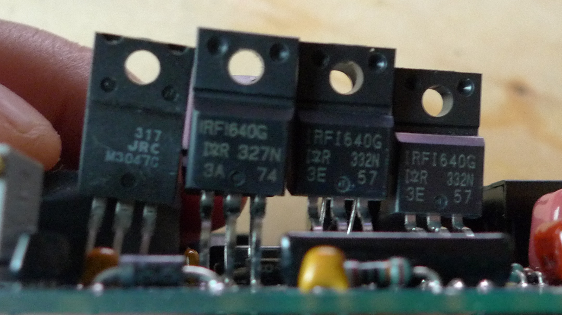
And below are views of the TO-220 devices which are folded over in the top-down photo:

We continue this month with the campaign to get Nava Whiteford permission to buy a SEM. Thanks again to Nava for providing another interesting ware!
well judging by the 100V MOFSETS and the CPLD, im going to throw a guess at the wall and say a (soft?)PLC of some form.
kind of curious what the TI IC is just north of the relays is.
Looks a bit like a multi-axis CNC motor controller I once pulled out of industrial scrap.
Assuming that’s a second IR2101 under the bent-over I540N, those two chips plus the MOSFETs give you one H-bridge. The SN75C1168 is a dual-channel RS-422 transceiver. I’d say modbus-controlled DC motor driver but that theory doesn’t explain what the balance of the black connectors are used for.
I tried using Photoshop to pull out some of the murky chip labels, but the resolution (& JPEG artifacts) are too coarse.
The 28 pin DIP below the Xilinx part appears to be a Microchip PIC, 16F??? (c. 2004). The 8 pin DPI below the blue cap on top reads ?352, but I couldn’t make out much more than that.
The black boxes across the bottom look like RJ-45 jacks, frequently used for internal wiring in 3D printers. I could imagine the relays are used to switch which device is controlled by the H-bridge. 2004 is just a bit early for consumer the 3D-printer craze, but it clearly looks CNC related.
It was probably a relatively low-volume board. By 2004, high volume board builds were SMT.
The chip to the left of the IR2101 appears to read “TLC2272CP” which is a dual op-amp. No big clues revealed there. The PIC looks like either 16F73 or 16F72. The 8 pin chip at the top below the blue cap has 5 characters printed on the center line of text, ending in “053,” but I can’t think of any 8 pin ICs that end with “053.”
It looks like a Gecko stepper motor drive board,certainly circuit wise.
or one derived from the “5 Microstep drive CPLD tutorial” that Mariss released a few years ago.
Are there enough MOSFETs or half-bridge drivers to run a bipolar stepper motor?
In any case, thanks for the mention of the “5 Microstep drive CPLD tutorial”, it is an interesting document. Googling the title quickly turns up a PDF but I won’t directly link any as many of the sites look dodgy and certainly none seem to be the legitimate original source.
why does this leave me think it’s somehow related to POTS ?
That also hit me as wellt — the two green jacks look like may be RJ-11/14 along with the
dual relays to control on-hook/off-hook.
However, I don’t notice any DTMF decoders/modem components…
MOSFETs? May to trigger a phone ringer?
Not sure what the five black boxes on the bottom of the first picture are? LEDs?
Best guess is some kind of telephone line interface.
I don’t have a better guess than anybody above, but those green connectors looks like the male end of RS485 quick-release connectors we commonly see in SCADA applications. That lines up nicely with the SN75C1168, which can be used in RS422 or RS485 applications. Wish we could see those black connectors better, but I do suspect they’re RJ45 or similar.
That’s probably a 34063 switching regulator at the top. The green connectors look like the male half of the two-part screw terminals Scott’s talking about and the five black ones are probably RJ-11.
Assuming the RJ ports aren’t being used for power transmission, I’m thinking it’s a local controller for something like an aftermarket tool/pen changer. The two-conductor-looking green ports on .200″ centers would be line and a dc motor load. The RJ ports might be assigned such as one for indexing/homing, one for e-stop, one for the commanding controller, one for a guard switch and one for a manual control pendant. The CPLD may provide hardware counting of, say, quadrature-encoded rotating discs and maybe receive some of those input signals (lazy port from another MCU?). The PIC probably doesn’t do that much more than count.
The MOSFETs initially made me think motor control, but there just doesn’t seem to be enough high-current I/O to support that.
I’m going to guess that this is part of a proximity card/door access control system. These would be daisy-chained on an RS-485 bus to talk to a central controller, and the green connectors are probably power (two to also allow power to be daisy-chained). The CPLD handles the timing-sensitive modulation and demodulation, and the PIC does high-level control and communication on the 485 bus. The big black can is the coil antenna with a pair of the MOSFETs driving it. The relays are for operating electric door strikes through the other RJ-11/45 connectors. It is however missing any kind of LED or buzzer that would typically be used to indicate status in such an application, though, so I’m not entirely sure.