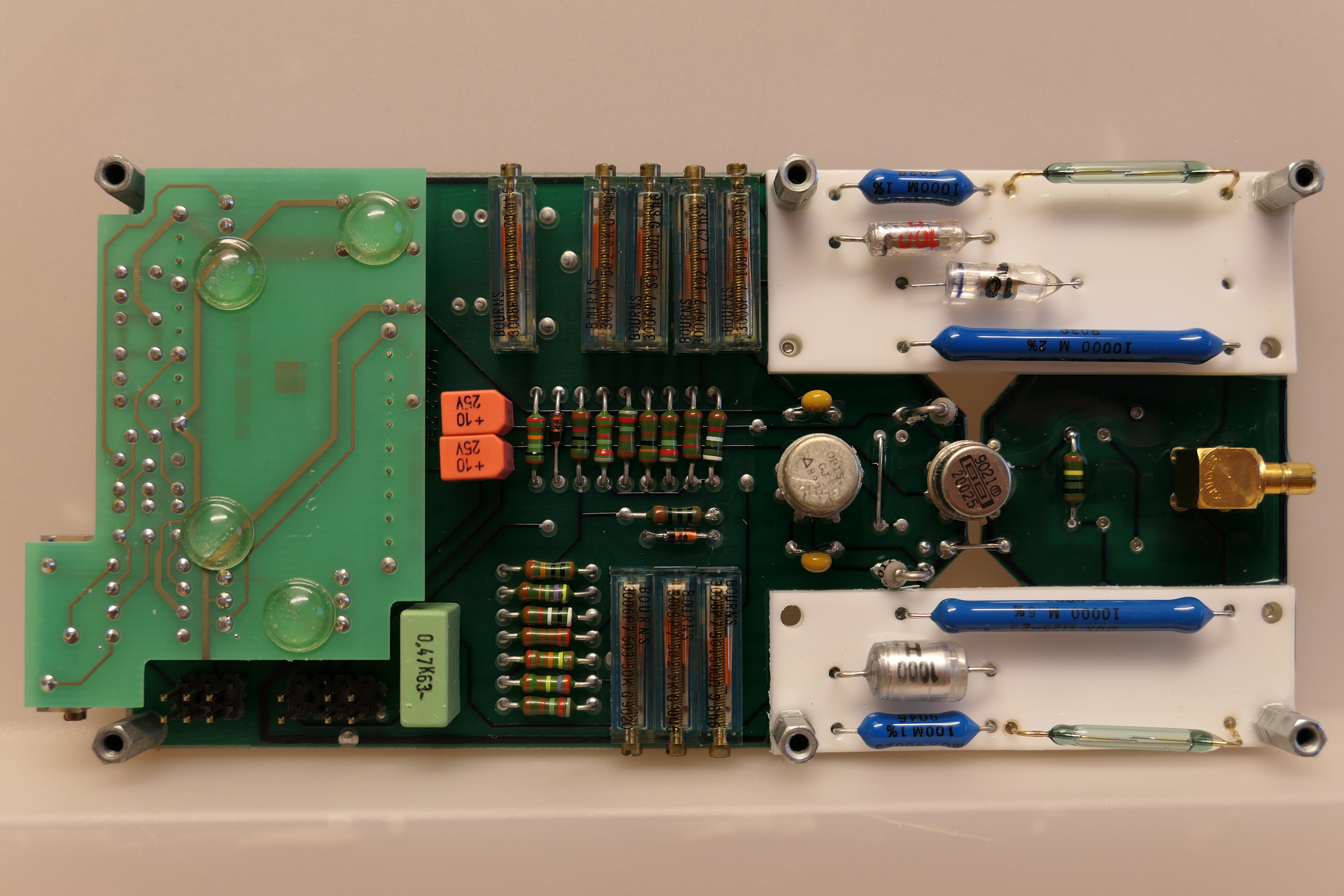
The Ware for September 2017 is shown below.
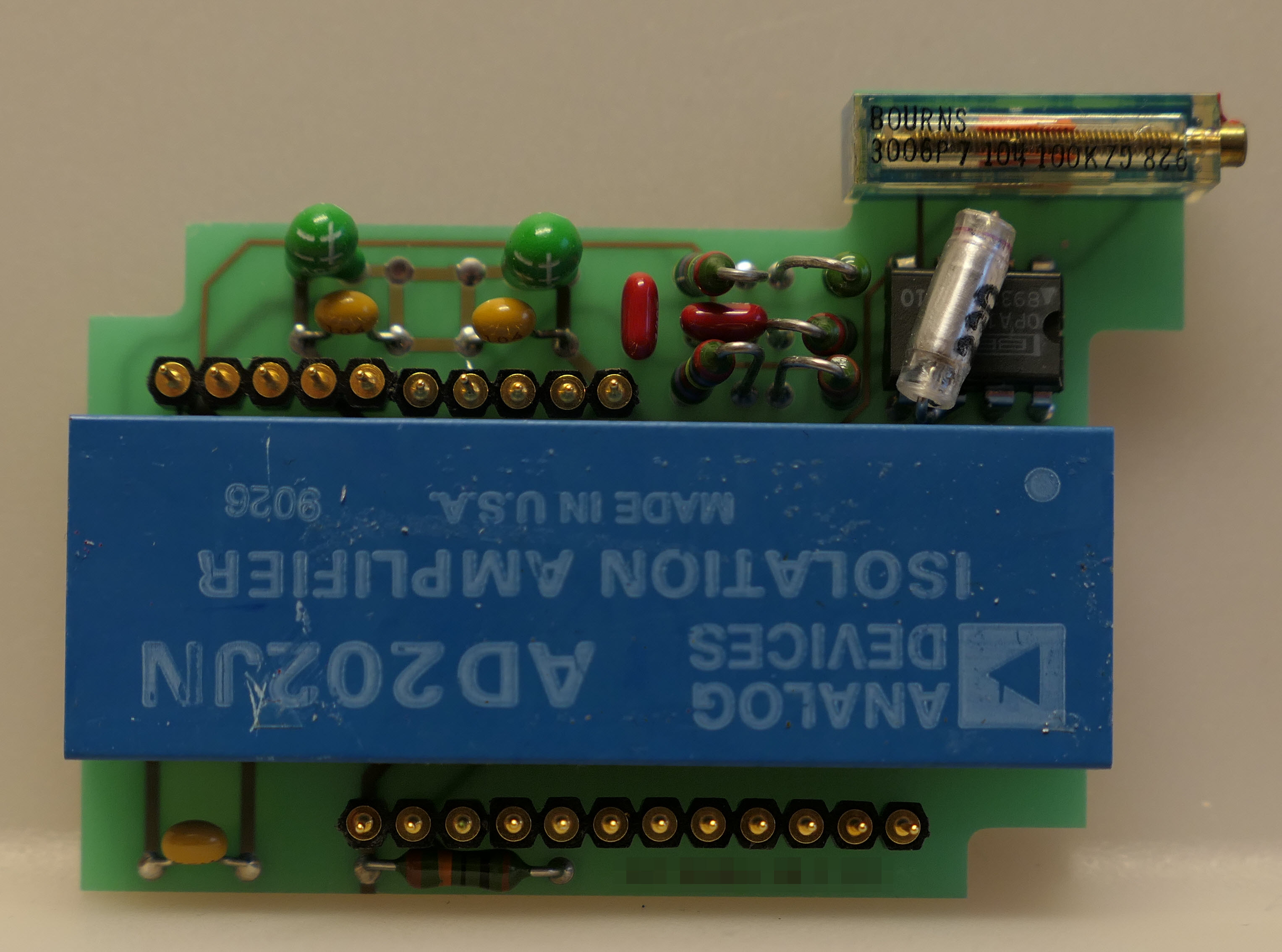
And here is the underside of the plug-in module from the left hand side of the PCB:
Thanks to Chris for sending in this gorgeous ware. I really appreciate both the aesthetic beauty of this ware, as well as the exotic construction techniques employed.
wanted to say high voltage(1000:1?) differential probe, but isolation amp is barely 5KHz
The construction using a fully separed PCB and white spacer material (ceramic) suggests that the designers cared a lot about reducing leakage – but that’s a given since there are 2% 10GOhm resistors on there. The layout looks deceptively differential at first glance, but
My initial guess was some utlra-low-current amp meter or electrometer, but looking closer at the circuit I think the connector is an output instead of input based on the orientation of the OP15. Maybe a precision low current source?
I wonder how the system around the board looks since it must have a way to trigger the reed switches at the sides. Looks like some kind of range switch, but it’s hard to make out any details of the circuit.
Oh, one more thing I forgot to edit in: There seems to be partial conformal coating, another indication that someone cared a lot about reducing leakage.
Hi Ingo, sharp eye, but looks like pin 3 on the OP15 (noninverting input) is definitely going to the other, Burr-Brown, TO-99! So it would be an measuring circuit after all. Perhaps it’s a tester specifically for leakage—MOSFET or IGBT tester?
I am guessing a “megger”, a high resistance insulation tester. The reed switches might be some form of safety interlock, requiring a cover with permanent magnets to be closed. “Meggers” generated high voltage to energize the conductors under test.
A quick first guess, maybe part of the power and modulation level feedback chain of a high power radio transmitter. Given the 1991 date stamp, most likely AM or maybe FM.
Looking at the bandwidth of the AD202, probably not modulation feedback. Feedback for power output still feasible though.
The reed switches may just be a safety feature to prevent high voltage sources from reaching the lower voltage side when the module is not seated where it should be. Though I’m not sure how a 0.7mm gap works at the voltages warranting this level of HV isolation.
the reed contact may be rated for voltages as high as 1,5kV as a quick search on farnell showed for me. they are probably not filled with air :)
EGC input stage? maybe?!
Or another medical measuring device.
Maybe it’s an isolated ultra low current to voltage converter. Something similar to this? http://www.dtic.mil/dtic/tr/fulltext/u2/a225033.pdf (CURRENT-TO-VOLTAGE AMPLIFIER WITH A HIGH VOLTAGE ISOLATED INPUT)
This is appears to be a biopotential amplifier, and they have strict safety requirements, especially if they use a driven component for potential sensing. The AD202 was used extensively in biopotential amplifiers and sensors of various sorts. It could be the sensing front end for a single ECG lead of a semiautomatic defibrillator. It would need to be able to survive the currents involved in the defibrillation stage, with high-resistance ground isolation and leakage control. The reed switches would allow the strict potential isolation required by that application.
The AD202 was used extensively in biopotential amplifiers and sensors of various sorts. The 5kHz bandwidth was more than enough to ECG.
I guess it could be a Charge amplifier, maybe to be connected as a preamp for a piezoelectric force sensor?
It looks like a very high-gain front end with a very high input impedance. I guess the two reed switches (normally closed?) open only when the ware is inserted into a larger device, protecting the very sensitive inputs while unconnected.
Another reason for the reed contacts might be this: If it’s a charge amplifier, it’s an integrator that needs to be reset every once in a while. The reed contacts could be part of a reset circuit, with the electromagnets used to actuate the switches off the board, somewhere else in the system. This would, however, have to be very carefully designed: The magnetic field might couple into the sensitive input circuit.
The AD202 isolation amplifier was probably used to reduce interference, not for electrical safety – the board seems to lack creepage or clearance distances as would be needed for a medical front-end. So I’m guessing towards an industrial or automated test system.
TO-99 ftw. The passives and the coax connector make me guess it’s a European design. As do the screws and bolts, which look pretty metric to me.
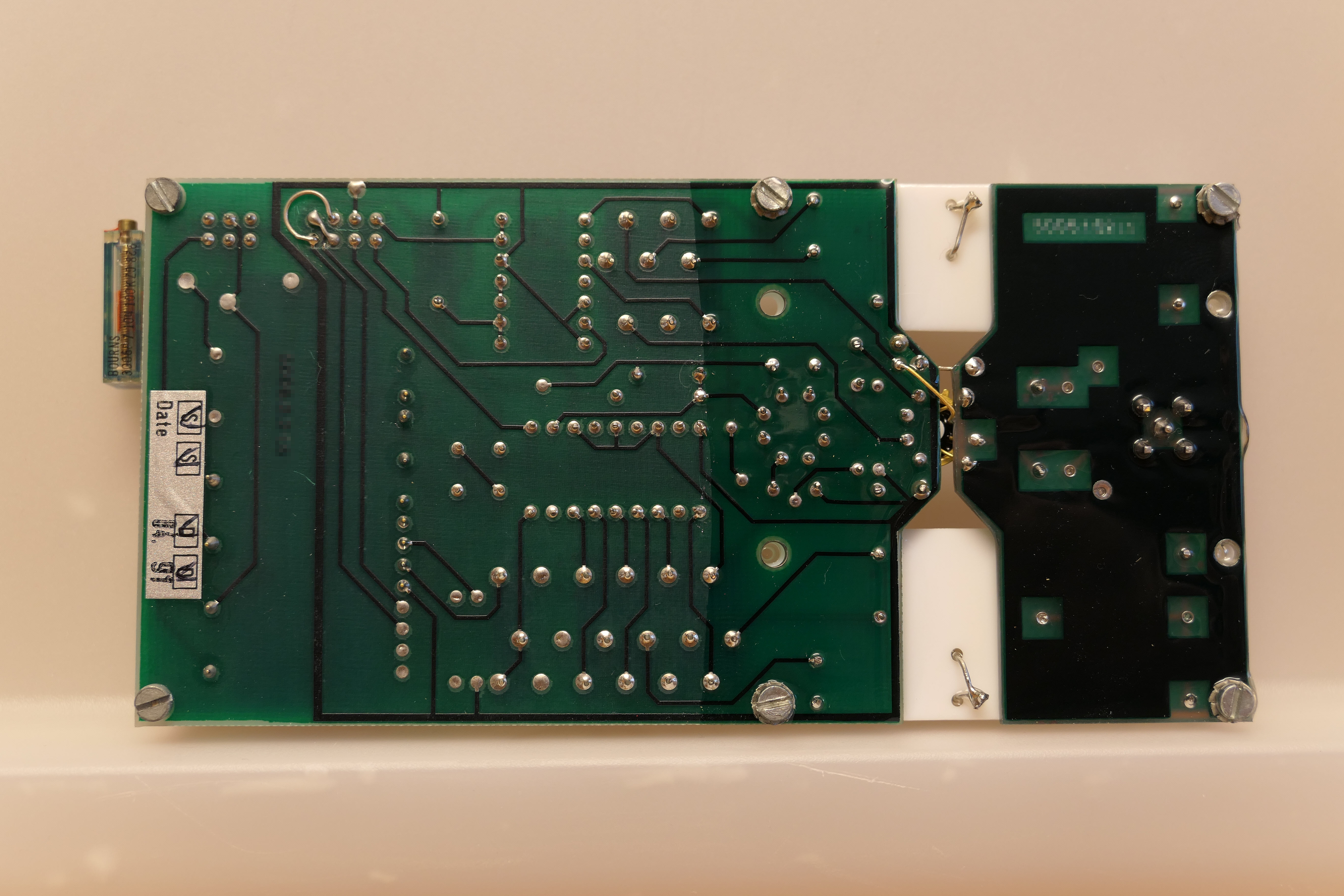
The large guard ring around most of the larger PCB (both TOP and BOT) probably was designed with a lot of good intentions, but it might do more harm than good. I’ve once helped debug a board with a ring like this, and the circuit got messed up badly – it’s a large one-turn transformer winding for any field that reaches through its area.
I still have a hard time guessing what the ware really does because most of it seems to be a resistive network.
… and let’s not forget to admire the passive components. It’s all to easy to say “TO-99 FTW”, but as an analog developer, the capacitors deserve the same honor, so here it goes: “polystyrene caps FTW!” Sadly, they’re just as obsolete as TO-99.
I don’t know what it is but looking at the bottom of the board it sure looks like a lot of poor solder joints. A significant number of the device leads appear to have poor wetting. There are few suspect joints on the top of the board as well.
What I do not understand is the wire bridge between the two boards. I mean, they are separated by this TO-99 housing and the ceramic circuit boards… and then there is this wire bridge. Was that designed to be removed after installation perhaps?
That looks like a ground tie to me.
Yes… connects groudn on both sides. So they might have left the PCB in one piece also and skip the ceramic supported flying wire construction.
Perhaps the ground strap is just for testing. Remove before installation.