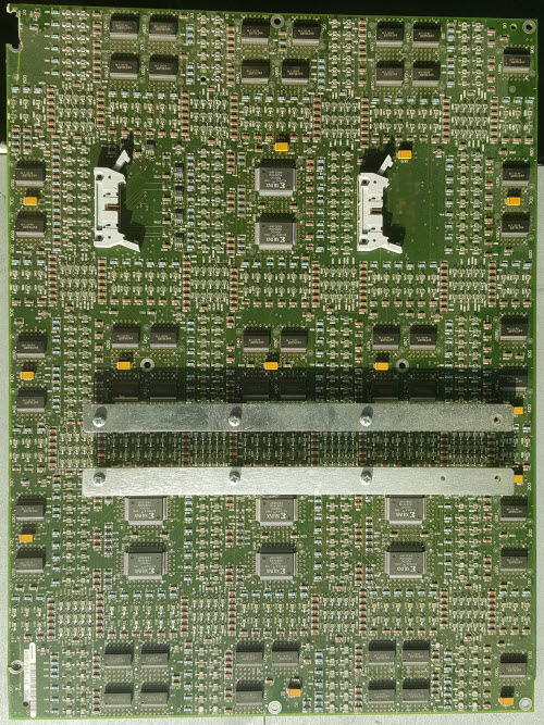
The Ware for November 2017 is shown below.
Happy holidays to everyone!
This entry was posted on Monday, November 27th, 2017 at 5:25 am and is filed under name that ware. You can follow any responses to this entry through the RSS 2.0 feed.
Both comments and pings are currently closed.
At first glance, it look like a LED array panel for advertising screens at football stadiums (stadia?) the 74ABT16244 16bit line drivers for the LEDS controlled by the Xylinx devices. the metal strips may hold a heatsink panel againts the backside of the LED chips..
You can see all the LEDs on the board. I can’t figure out what would use the grid pattern with the denser intersections.
looks like it can be tessellated horizontally, but not vertically (too many LED / too much distance where the panels join).
Older Asram display? P20 or P31.25
It can be tessellated in either direction. One of the connectors is an input and the other an output, so that multiple units can all be connected together to make a display.
So I thought I had something when I noticed that Bunnie neglected to pixelate the barcode sticker on the bottom left corner. It decodes to “N00441663” but web searches on several search engines didn’t turn up anything meaningful with that number. Maybe it’s just a serial number sticker.
Obviously it’s some sort of LED panel but the arrangement of LEDs is puzzling. Not sure what you’d do with a grid arrangement like that. It looks like the LEDs are down facing ones mounted over holes in the PCB to show thorough the other side. That makes me wonder if there might be more LEDs on the other side to form a full grid. But that doesn’t make sense with the denser LEDs at the intersection of the rows.
If you stack them vertically the rows wouldn’t be evenly spaced as the LEDs are six rows deep above the upper intersections and 9 rows deep between the rows, not 12.
There’s about 49 driver chips with 16 outputs each, so that’s enough to drive 784 LEDs individually. I see about 500 LEDs on the board. Not sure why you would need individually controllable LEDs in an arrangement like that.
Puzzling….
Date codes on the Xilinx ICs look like 1993.
My guess is a module from an older LED display board that could only show 7-segment-like numbers, horizontal and vertical lines, and maybe crude characters (rounded corners). E.g. used for sports betting, stock market, train station or airport.
Alternative theory: Display nodule of largest ever Snake game ;-)
1993 matches up with the first hacked display for MITs Green building, but I think this board is more than that hack needed. Tetris on that building was later.
Clearly part of some sort of semi-custom signage. Would love to see it lit up.
Sounds like an airport flight display from the comments above.
If those connectors are used for flat vables, teh cables will be in the way of the LED’s. Those busbars can connect to the right of the picture, but the connectors only can take some wireless module.
But the busbars also blank out LED’s… so strange.
There appear to be holes behind each LED, so I think they are shining the other direction, so this is the back.
Couple of observations:
1) Power supply to the board does not appear to be on the pictured side (with the possible exception of the bus bars, but the busbar connections in the shadows don’t look like they exactly connect for power).
2) With the LED’s facing the other side, the pattern looks completely orthogonal with higher density LEDS at crosspoints (points already made in other comments above).
So my guess is a 5×5 tic-tac-toe-like board which lights up the row and column dividers. Or it could be a board from a lighted control panel for some industrial equipment.
So before I read the other comments or zoomed in, the connectors, plus the small xilinx chips, reminded me of some enterprise networking backplanes – but as others have noted, there are clearly rear facing LEDs (through holes in the PCB) so it would be one awfully bright bit of networking kit :).
My guess, based on the apparently constrained matrix, is a missile from something like electronic road signage, especially construction signage. I could imagine you might position corners of characters in the high density areas (if they’re individually addressable there, or maybe you can light up subsets to get angled corners) while letting straight lines be shown by the more simply switched linear segments. That’s my guess, anyway… My first time guessing on one of these.
Hoping that there’s just a lot of traces on the back or perhaps inner layers, now that I look closer still: that’s a ton of vias and a lot of traces I can’t follow. Possible that there are some LEDs on the back, too, though they’d also need their resistors, since they appear approximately balanced on this side. Also, a ton of those 8 bit buffer drivers, though I suppose those might be used/abused as LED drivers whether individually or in sets or 8 (tie all high and just fool with oe)
Can I just say, I really love the nice grid system to the component numbering? Hundreds digit vertical (on left), tens digit horizontal (on bottom) – so presumably/potentially service might involve finding a numbered component so such a “map-like” component index would be useful. That, or the designers were trying to woo me with their design… (I mean, it makes sense to have orderly numbers for repeated sub units, but I don’t know if I’ve seen one like this with a group numbering before, I wish boards I worked with did…)
I will bet that there are LEDs on the back. If you follow the component numbering we cannot see D001-D009 or D020-D029. I am guessing those are on the other side.
Maybe an old RGB module for a LARGE format screen.
The different densities could be compensation for different light intensities.
It seems there are several pairs of columns, appearing to be different colors, of bottom-emitting LEDs. Then there are some 3×5 matrices, probably for character display. It is probably a console display for some kind of audio/video equipment like an audio mixing board, or industrial control.
It seems like very costly way to light some LEDs, however, to have all those FPGAs just to light some indicator lights and 16 character cells… the Xilinx FPGAs are $10+ each. It would be more logical to use a serial-to-parallel configuration, with SIPO shift registers driving the LEDs unless the update rate is extremely high.
Some sort of process industry equipment. I am thinking it could show part of the core of a nuclear power plant with the position of the control rods.
It’s a display LED panel driver for an RGB LED display, circa mid 2000’s. Used for large format signage.
That was a tough one!