The Ware for May 2019 is shown below.
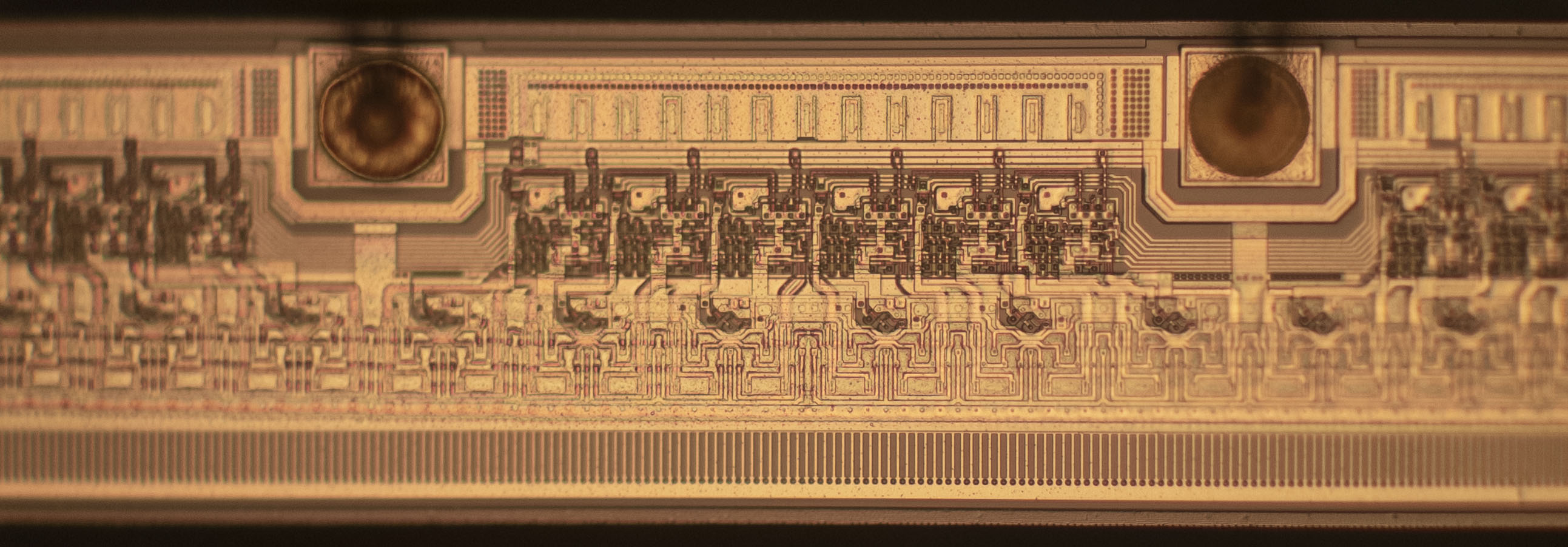
It’s always tough to calibrate how much of a chip to show to make it identifiable, but not too easy to guess at the same time. Let’s see how this one goes…
This entry was posted on Thursday, May 30th, 2019 at 5:41 pm and is filed under name that ware. You can follow any responses to this entry through the RSS 2.0 feed.
Both comments and pings are currently closed.
Seems like a TFT, OLED or E-paper row/column driver to me. Circuitry from the top row looks like a shift register + latches and the bottom row are buffers
Looks like there’s seven ‘address’ lines and two ‘power’ lines. Some kind of 128 line multi-voltage decoder/driver?
I’m going for an LCD row driver. The column drivers are more complicated (at least for a multi color LCD). The row driver is select-only, the column driver will have (non-linear) DACs.
And this chip does not have the complexity of a DAC, S/H, driver etc.
Maybe it is part (row or column driver) of some memory IC (EEPROM?). I don’t thing it’s part of display – most of them are bare-die flip chips, and here on the top are bond wires.
I think the lower edge is an actual edge, which would make this something like a 1 dimension CCD or other sensor? Perhaps like you might find in a scanner? I remember someone using a sensor like that to make a rain detector (circa 1983).
thermal printer head driver – for a label printer, maybe?
I’m thinking drop on demand driver or something similar.
A caliper perhaps?
That was my first thought, too. Those often have an ordered array of capacitive pads, but I would expect some kind of grey-code layout. I don’t see that.
I’m going to guess this is part of a die from a contact image sensor (see https://compo.canon/en/product/cis/) used in document scanners. Older scanners generally used 1-dimensional CCDs, but the bond wires on those are usually positioned on either end of a long CCD. This photo looks like a section of a very long and thin die with bond wires along one edge, which seems to match up with the contact image sensors I’ve personally seen (https://i.imgur.com/V7fHe7m.jpg).
This. Just look at the structure of ELIS1024 here http://dynamax-imaging.com/products/line-scan-product/ . It’s not that part, but they’re at least cousins!
not remotely close at all
That looks like the back of a Variable Frequency Display “VFD” Driver.
Mfgr unknown, Fab Plant Unknown, Date of birth unknown!
About a decade ago I helped out debugging a fingerprint sensor ASIC using an Infared thermal imaging microscope. The layout of this IC is remeninescent of that particular finger print sensor. This was before the fingerprint sensors used a matrix layout and you had to swipe the finger across the sensor array. Hence my guess is a fingerprint sensor array from Fingerprint.