The Ware for September 2021 is shown below.
This ware was kindly contributed by @marcan42. I’m really impressed at the quality of the camera work for the wares!
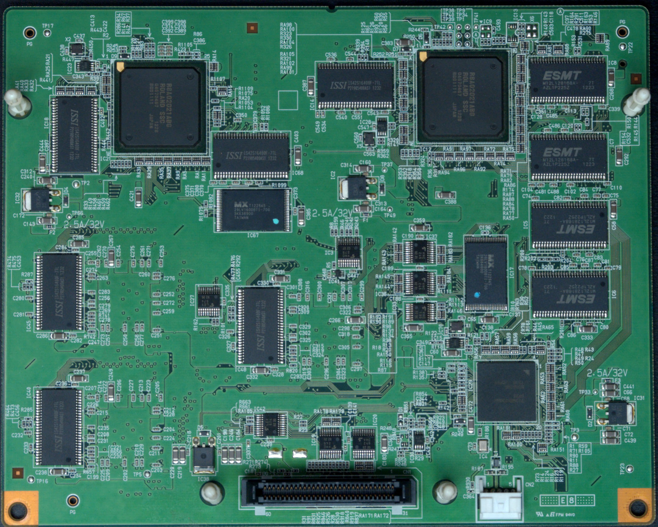
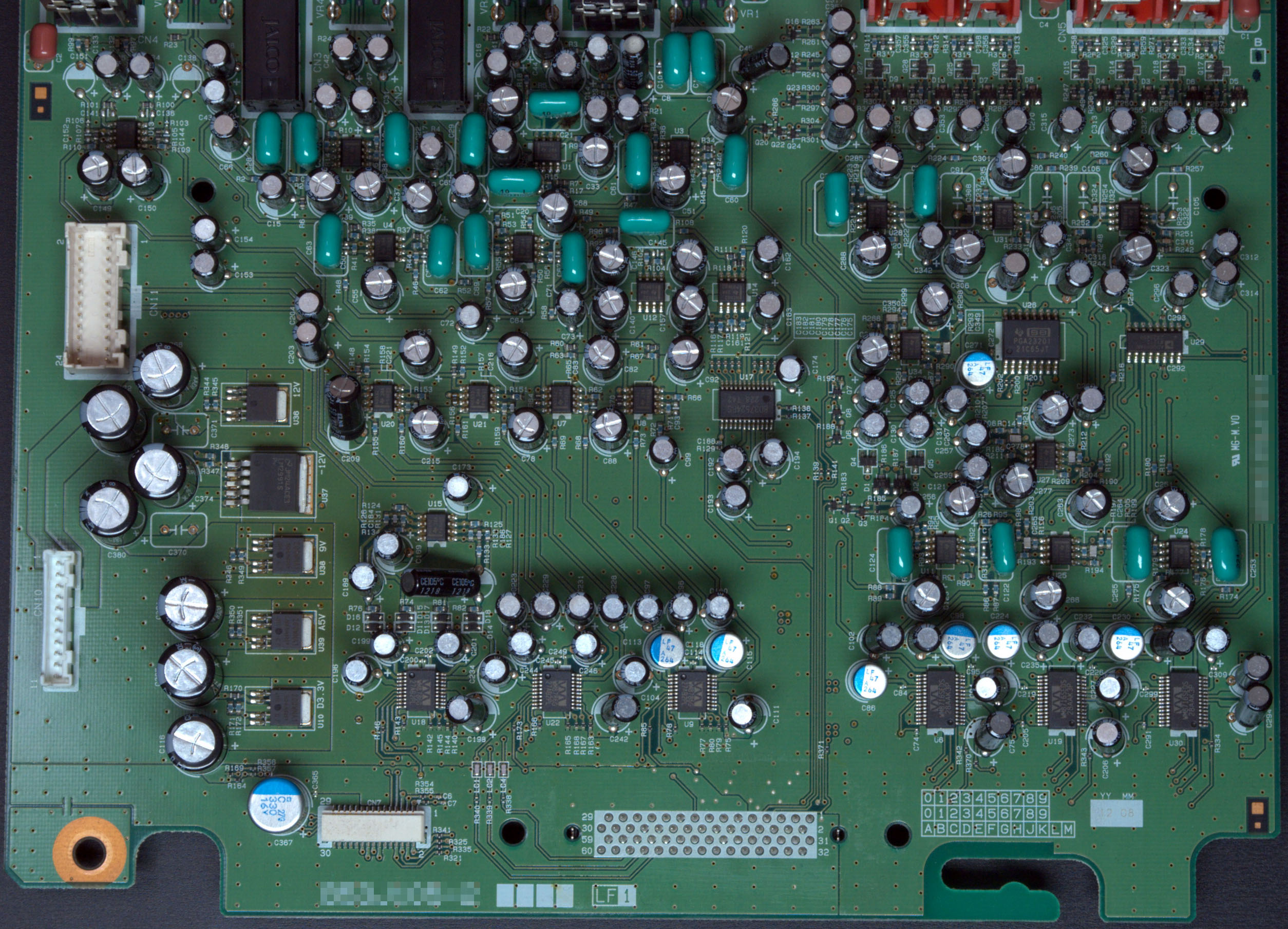
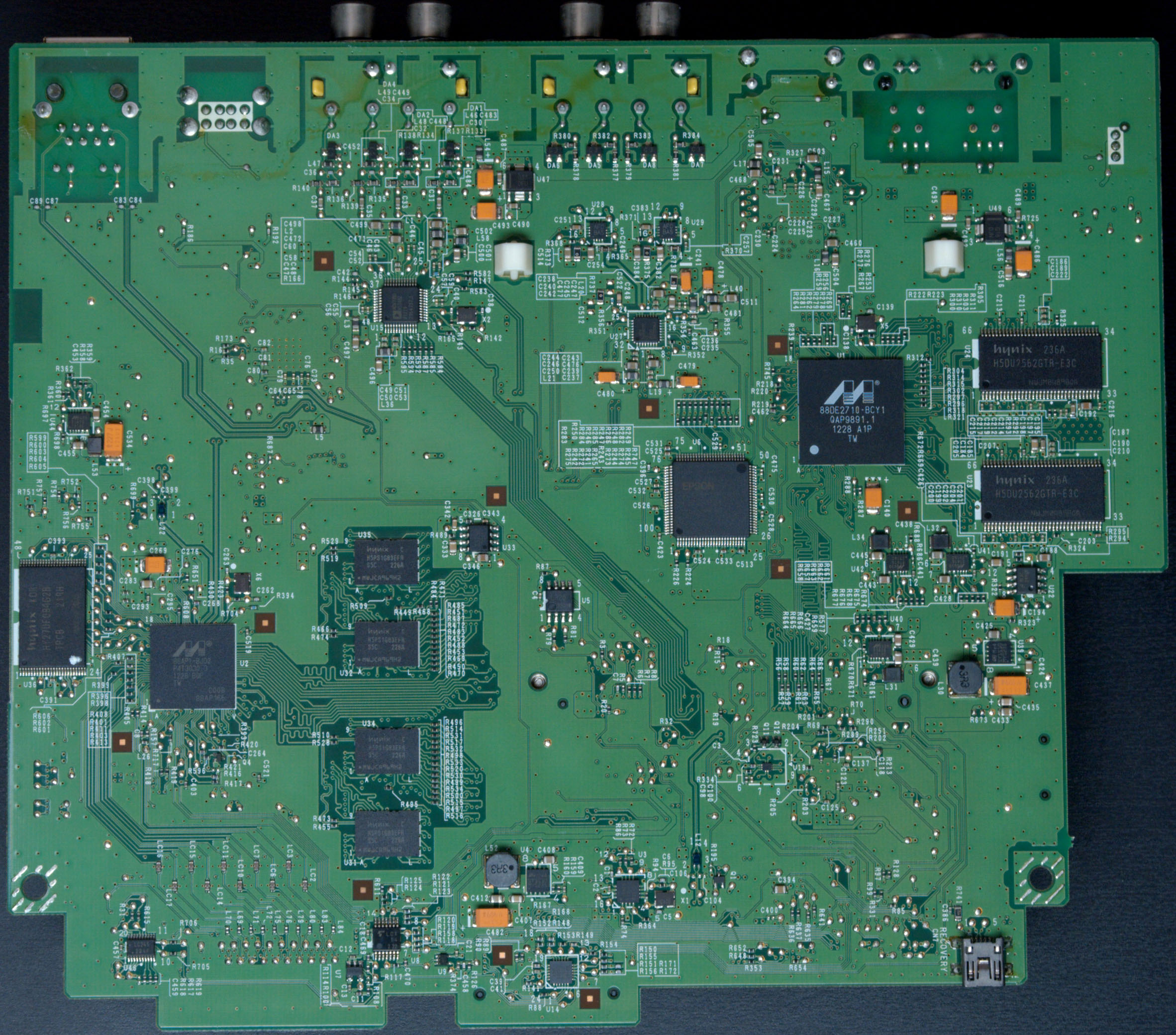
These are just a subset of the boards from the ware, but I suspect it’s more than enough to get a positive ID. The digital board is a bit more telling, but I find a well-designed analog board to be too attractive to pass up posting. I also love the slightly browned regions evidencing the hard life that the linear regulators experienced, filtering out all that power supply junk to create a clean, smooth power rail suitable for audio. If nobody can figure this out, there’s another board I’ll add to the set which might be helpful.
Bonus points to anyone who can come up with a good theory for the ~3mm 45-degree angle cutouts sprinkled around the digital board’s power plane pours. I can’t come up with any consistent rhyme or reason for them to be there, so maybe the engineer was just going for style points? Nothing wrong with going for style, but perhaps I missed the memo on some sort of black magic with respect to detuning resonances in power planes, or something like that.
Update Oct 7
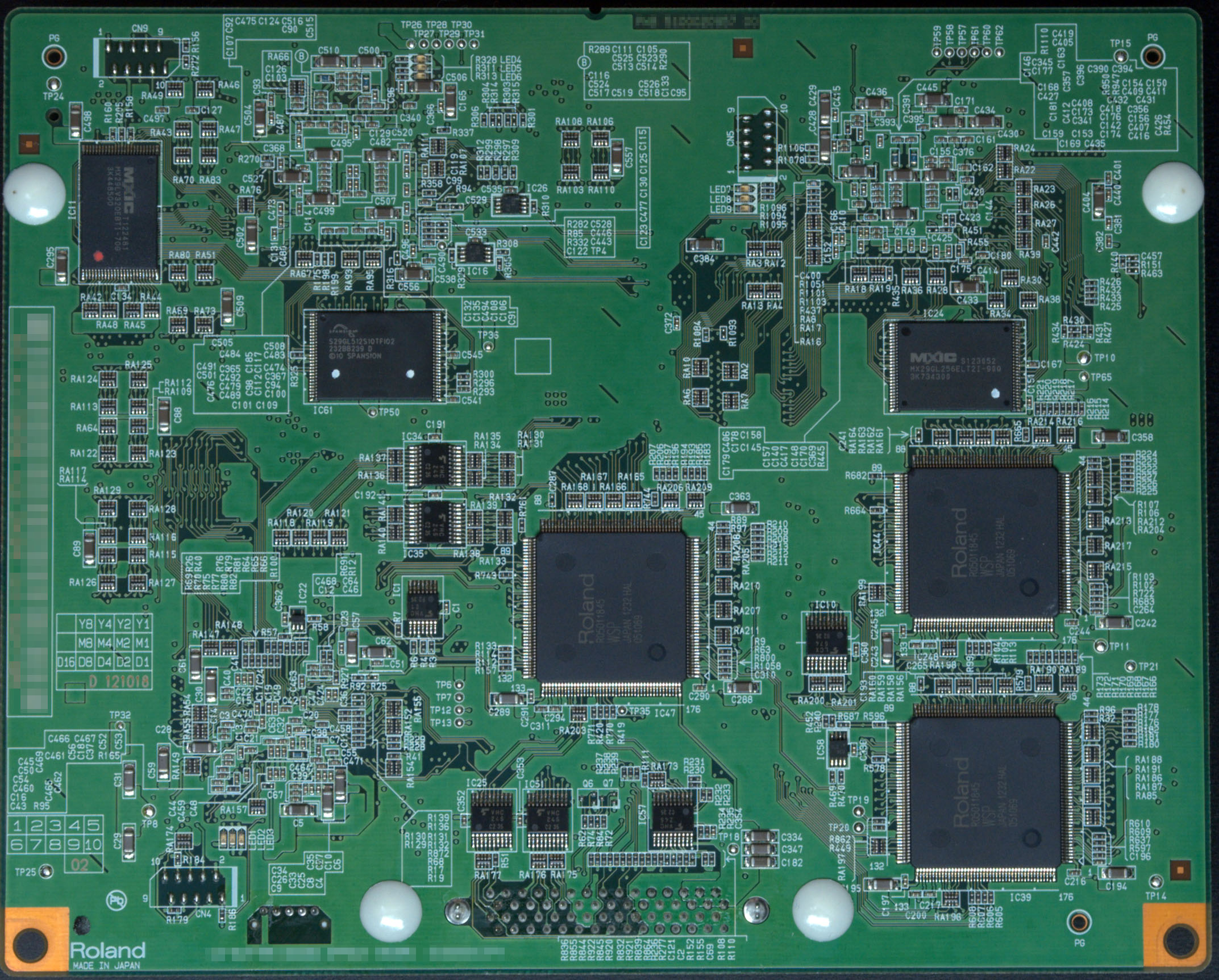
It’s been interesting to see where the guesses are going, but unfortunately nobody is getting close. So, here’s another important board from the ware:

Notes on some so-far fruitless paths:
The Roland logo, of course, leads one to think of synthesizers and samplers.
I’m finding the R8A02021ABG and R05011845 ICs mentioned in a fair number of products, but I’m finding no matches for these PCBs yet.
The squareish boards and my estimate of their size suggest a rackmount synthesizer or desktop synth or sampler rather than full-sized keyboard. I think I’m reading late 2012 date codes on some of the ICs, but I’m not seeing these PCBs inside products from the Roland catalog circa 2012 (a few years earlier and still in production; a few years later and still using old stock of ICs).
Of course, Roland also makes desktop CNC cutters … but to my knowledge, they’re not laden with audio ICs. :-)
Maybe a digital audio mixing console? The analog board seems to have too many RCA-looking connectors for that though, XLR would be more common in that space.
Definitely has a certain feel to it, even seeing the thumbnails from the main page was thinking “Japanese A/V equipment”. First impressions were…
* Some kind of digital audio workstation, but the modern-enough ones seem to be too physically compact for that
* Large upright piano, which extend a good way back, unlike a keyboard which wouldn’t have enough space – but it has far too many outputs, and having inputs too makes this unlikely.
Speaking of which, the analog board has 3x WM8716 stereo DACs and 3x WM8786 stereo ADCs, so there’s at least 3 (stereo) inputs and outputs. I’m also guessing it’s not something massively complex as judging by the connectors on these two boards, they look like they’re supposed to mate with each other but not a whole lot else; there might be another one designed to sit in the middle of the “stack”, but I’m guessing the rest of the boards are all things like display, buttons, power supply, extra connectors, etc.
Anyways, this leaves…
* Rack-mount effects unit, but if Roland makes (or made) any of those I can’t find any sign of them
* Rack-mount MIDI synthesizer (or “sound module” as they call them) – didn’t know these were a thing until just now looking at Roland products: for example, the JV2080 (http://www.vintagesynth.com/roland/jv2080.php) or the Integra 7 (https://www.roland.com/global/products/integra-7/). It can’t be the Integra, or the JV-2080/1080/880/XV-3080 though because the connectors at the back don’t match up to what’s on the analog board. The analog board also has 4 regularly-spaced right-angle pots, judging by the “VR” silkscreen labels, which also doesn’t match up to the front panel or back panel of any of the “sound modules” I can find.
Those analog board connectors/controls didn’t match up for any of their “sound modules” or sufficiently-large synths that I could see.
From right to left (from the outside), the analog board connectors should be, best guess…
XLR
Pot
1/4″ jack
Pot
1/4″ jack
Pot
XLR
Pot
(gap)
RCA
RCA
(gap)
RCA
RCA
Too few channels and too much processing power for one of the pro mixers. My best guess overall is one of their pro digital recorders or a DJ mixer (such as https://s11234.pcdn.co/wp-content/uploads/2019/12/roland_dj_707m-front-back.jpg.optimal.jpg) as those have believable form factors + the right kinds of connectors and controls on the side. Didn’t find a specific one that fits, but also didn’t look through the entire back-catalog.
I noticed the datecodes:
2012-10-18 on the digital board
2012-08 on the analog board
Nothing from here https://www.roland.com/global/company/history/ matches for 2010-Present.
Could be a Boss/Edirol product too.
The / cutouts seem like a manufacturing process improvement, as they only exist in places that have large unbroken copper fill without vias. Stress relief to reduce warping of the prepreg layers before they’re bonded together?
My thoughts exactly on the stress relief. Figured I would look for this first before posting the same.
Never seen stress relief structures before on a full-size FR-4+copper construction circuit board? Copper is soft and malleable so it handles CTE mismatch pretty well. The analog board has huge copper pours and no cutouts. Could be that they are using an unusual thickness of foil, maybe…??
Hm, if it was in the prepreg before lamination, they’d also have the double-challenge of sourcing prepreg that has holes pre-cut, and aligning them well, and designing the circuit board around that. Overall, it’d be a pretty complex process. Could be that they are using some sort of a plate-up process and they need some non-plated areas to put sacrificial electrodes or something, but I also have never heard of that, now just guessing wildly.
I would not say stress relief per-say; more they were worried about the bond of the foil and wanted to use the solder mask to glue it down. Moisture may be a more plausible threat then thermal stress. As this is not a common technique presumably the is not much actual risk; or this is not effective. Possibly an hang over from designing for early PCBs?
Roland RSS-303 Sound Space Ambience System
Just curious… why so many electrolytic caps. Are they using them as bypass caps?
I presume you’re asking about the analog board.
While some do look like they are being used as bypass caps, I’d say most of them look to be used as DC blocking caps for audio signals.
Different stages are often AC-coupled so that the DC offsets/biases of each stage aren’t amplified. In order to get flat responses down to 20Hz at audio impedances, a fairly beefy series cap is needed between active stages. I do see quite a few places where signal-like traces are terminating into the caps, so that’d be my guess.
On the newly-posted board, the Nvidia card appears to be a “12B10376 Tegra 2 VCM control card”:
https://www.ebay.com/itm/232668271345
And NVidia VCM appears to be Visual Computing Module, highlighted (but not exclusively) for in-vehicle systems including infotainment and digital instrument clusters:
https://www.nvidia.com/en-gb/design-visualization/visual-computing-module/
The two channels of CVBS (Composite Video Blanking and Sync) and the HDMI at the top would be consistent with some kind of video processing, and the 88DE2710-BCY1 is showing up as a video-processing IC:
https://www.ebay.com/itm/123875115730
Roland does have a number of video processing and editing stations, but I’ve not found any that look quite like this.
CN10 says SATA, so this connects to local storage.
I’m not feeling like any of this has got me closer to figuring out the product.
It’s a satellite tv decoder. Composite + HDMI outputs, Composite input, presumably to do picture-in-picture and/or make it easy to switch between satellite and video game / vcr /dvd player.
Interesting that only two connectors on the third board seem to have anything to do with the first two, and they are labeled “PREAMP” and “ROLAND”. These boards seem to be part of a pretty complex system, given the functionality I see on the third board: NVIDIA Tegra K1 compute module, Marvell Armada SOC, and Marvell 88DE2710 Digital Video Format Converter, and connectors for a fairly high-resolution LCD panel, USB WiFi module,
Interesting that only two connectors on the third board seem to have anything to do with the first two, and they are labeled “PREAMP” and “ROLAND”. These boards seem to be part of a pretty complex system, given the functionality I see on the third board: NVIDIA Tegra K1 compute module, Marvell Armada SOC, and Marvell 88DE2710 Digital Video Format Converter, and connectors for a fairly high-resolution LCD panel, USB WiFi module (seems unusual for professional A/V gear), and SATA hard drive.
I would guess that the third board isn’t designed or made by Roland at all, since I can’t find any Roland products with some of the features it has, and the one connector on it that connects to an obviously Roland-designed PCB is labeled “ROLAND”.
I’d agree that it isn’t a Roland product, it’s a Roland subsystem as part of someone else’s product. The Roland board is basically a bunch of DSPs which come from a Synth but they could have been used anywhere.
My hypothesis would be for car infotainment.
CVBS input would be for showing video from parking cameras.
HDMI would be for HDMI input
Satellite could be for satellite radio, those aren’t satellite TV tuner connectors (e.g. F-type)
The audio board is multi-channel which also supports the idea of quadraphonic or better sound.
Given that Roland is a Japanese company, I am going to go with a bold statement that this is the infotainment system from a 2012 Honda?
100% not automotive or industrial, the connectors they’re using are way too delicate. I’m leaning towards this not even being professional A/V gear, as most of that tends to avoid RCA connectors and use BNC connectors for composite video and XLR or 1/4in TRS jacks for audio.
True, automotive ethernet has additional screw/threads for handing vibrations. This is a desktop unit.
Is it a Tesla car?
At least the SOM with the Nvidia SOC seems similar to the one here:
https://www.pentestpartners.com/content/uploads/2018/01/trw-one-7.png
from https://www.pentestpartners.com/security-blog/reverse-engineering-tesla-hardware/
This tegra SOM (T30AGS-Q-A3) seem to also be used on the 2016 Honda Pilot and the Audi virtual cockpit. For the later the PCB don’t match at all. So remains some tesla and The 2016 Honda Pilot, though I didn’t find PCB pictures of either yet.
The Nintendo Gamecube?
aren’t these a couple modules from the Tesla CID?
nevermind, this feels very cursed.
so this has audio capabilities, and also satellite, CVBS, and AI video processing capabilities. this is so weird!
Nintendo Switch development kit?
https://i.ibb.co/z8FSGyP/switch-devkit.png
This is something of a wild guess, but could this possibly be from the GLM ZZ automotive head unit system? I don’t think Roland makes anything of their own that takes a satellite input and uses an NVidia compute module.
http://clynemedia.com/Roland/Electric_Car/Roland_ElectricCarSoundsystem_Gadgets.html
The SSC and WSP chips are the basis of a synthesizer core that Roland has used across many of their product line in the 2000s and 2010s. As I recall the SSP is a customized SH series microcontroller (I believe SH2 or SH3, the details can be found from various Roland service notes).
Overall: this is a strange combination, and while it is possible that Roland makes something that combines their proprietary synthesis hardware with satellite input and an NVidia module meant for vehicles, I’m hard-pressed to find what it is from their catalog.
To follow up — “SATELITE” could be a red herring here, as those could be connectors for auxiliary audio or something else like that. Still, I’m not finding any more leads for a device that contains an elaborate Roland audio synthesizer engine as well as an NVidia video processing board meant for automotive.
It’s interesting that the CPU board has a connector marked “Roland”, as if that module was not developed by the same group. I believe that from top to bottom we’re looking at Roland, pre-amp, and CPU boards.
Considering the video connectors, Tegra, and Roland chips, is this a karoake board of some kind?
Going to go with karaoke as well, haven’t found anything that exactly matches this but a lot of currently available karaoke systems seem to have a similar feature set and connectivity (several audio inputs/outputs using RCA or 1/4in TRS connectors, DSP, HDMI and analog video, USB, ethernet, wifi, built-in or external LCD) and a front panel with potentiometers for adjusting audio levels.
The inside of a pachinko machine? Lots of circuit boards, lots of audio hardware for the speakers and the Tegra to do the visual effects, seems to vaguely fit, plus the whole Japanese theme.
If its not some form of game machine/karoke device I would place my bet on VJ equipment or something else to control and or monitor a live video/audio performance.
The Video inputs are interesting also the fact that you get 2 display panel connectors plus all those video outputs. The S-ATA connector also suggests that stuff is being recorded or the device needs lots of data to play back which again would speak also for a Karoke machine that has aome high-end visual output.
Ok yea I’m pretty certain this is a Roland AV Mixer or some other AV product from Roland.
Something along the lines of this: https://proav.roland.com/de/products/v-4ex/
It would explain the need for an LCD panel, big storage and lots of audio and video in and output capability.
V-1200HDR https://static.roland.com/assets/media/pdf/v1200hd_brochure_3.pdf
Or one of the other multi-format Roland Video switchers that have an LCD. I do not think it is the V-4EX
At first I thought automative with the Tegra SOM (having seen similar ARM SOMs and automative dev kits packaged including for Tegra/IMX8). Some were used to pull multiple cameras and feeds to do computer vision, but the other Roland heavy boards would not make as much sense. Even the early tegra chips had a fair amount of compute and GPU capability. I haven’t looked closely at the specific Tegra SOM, but it could probably even do some of the video processing. Making it possible the Tegra wasn’t for the LCD but for some processing and to support the external control interfaces and applications.
Oh sure def. not the V-4X was just an example for the class of the device and the manufacturer.
Though it has to be rather small or there are more PCBs to this as the amount of video ports is quite low for a big mixer.
Hunting down the exact model would need some research time through their catalog, doubt that its a recent model.
The closest I’ve found is the Roland VR-5. Its missing the Ethernet though.
Gotta be from about 2010-2016 though.
A bit of a stab in the dark, but maybe some kind of medical imaging device, or other 3d scanner, using ultrasound?
My first guess would have been something automotive related, too. But as an automotive engineer I have to say that those boards are not automotive spec, neither are its connectors.
Similar Nvidia compete cards can be found in Harman headunits, like MIB II High (VW brands) or, or I am not mistaken, the NBT Evo (BMW).
(probably) Goodwell Technology Limited… is that a LCD monitor with gsync?
We’re nearing the end of the month — I think it’s time to drop a hint.
The right type of equipment was mentioned /somewhere/ in these comments, but nobody has managed to figure out the exact make & model yet.
PS: The brand of the equipment is not Roland.
My guess is this is part of a pick and place machine with optical part orientation correction.
Looks like a satellite receiver (probably JVC) with HD capabilites, ethernet for those video on demand feature and SATA for recording.
Nintendo Switch devkit/proto/etc?
The feature set of the device all seems to point to an medium/high end A/V device with an internal LCD, wifi capabilities and a satellite connection[?]. The hdmi port pretty much ruled out synthesizers or any industrial product in my mind. It seemed much more like a consumer device, for example a Karaoke machine as already suggested in the comments. With Roland and Karaoke both being instinctively Japanese, it made a good fit.
After some digging around Japanese auctions sites, I am pretty sure I have found it. It looks to be a Karaoke machine from Joysound. Which apparently uses a Roland “SuperNatural” amplifier. The type is JS-fR, rather than the JS-f1 which lacks the wireless network capability.
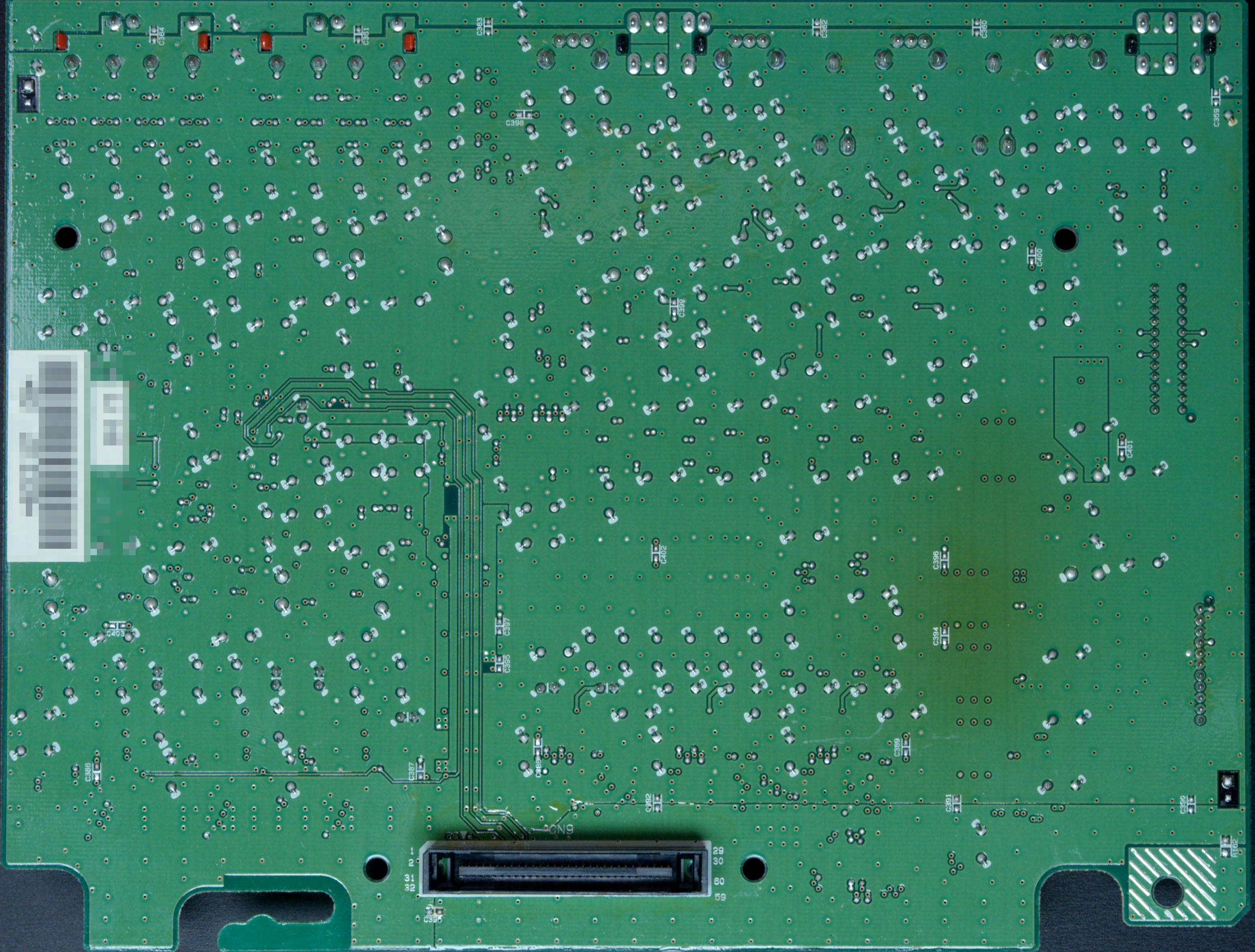
Was a little confused when looking at the usb and composite. In the image it looks like they are one-level height connectors. But the footprints indicate that they are stacked, matching the type. The board also has a manufacturing date which helped rule out some types of machines from the manufacturer. Made in the beginning of Sept. 2012 which fits with the release of the JS-fR in October 2012.
The “Satellite” connector turns out to be a connector for an external “RS-01 Remote control satellite” from Joysound. Which seems to be a complicated name for an IR remote extender, but I may be wrong. Looks to be a S-Video connector, an odd choice for a remote extender but might have been the best choice back then.
To nitpick the identical connector layout of the “f1” suggests to me it may well have shared the board with the “fR”. Given the Wifi module is not shown and its much greater popularity “f1” is probably the safer guess.
Yeah that’s a good point. The pcb’s are definitely identical, given that they came out within a few months of each other and the only difference between them being the case color and the wifi card.
My first thought was that they wouldn’t have populated the unnecessary connectors unless needed. But the 2 cent cost for a connector and solder wouldn’t have outweighed the advantage of needing to have only one type of board in stock.
Looking at the different amounts on sale right now, the f1 definitely seemed to have been the more popular option back then.