The Ware for October 2021 is shown below:
This one should be much easier to guess than last month’s ware; it’s strategically cropped to add a tiny bit of challenge to it. I’ll add some more views of the ware once we’ve got a correct answer.
I was really struck by the quality of the photography of this ware. jackw01 submitted a series of wares (this one included), which I’ll be sharing over the coming months. I have a lot to learn about photography, and I thought it might be of general interest to hear his answer on how this ware was photographed:
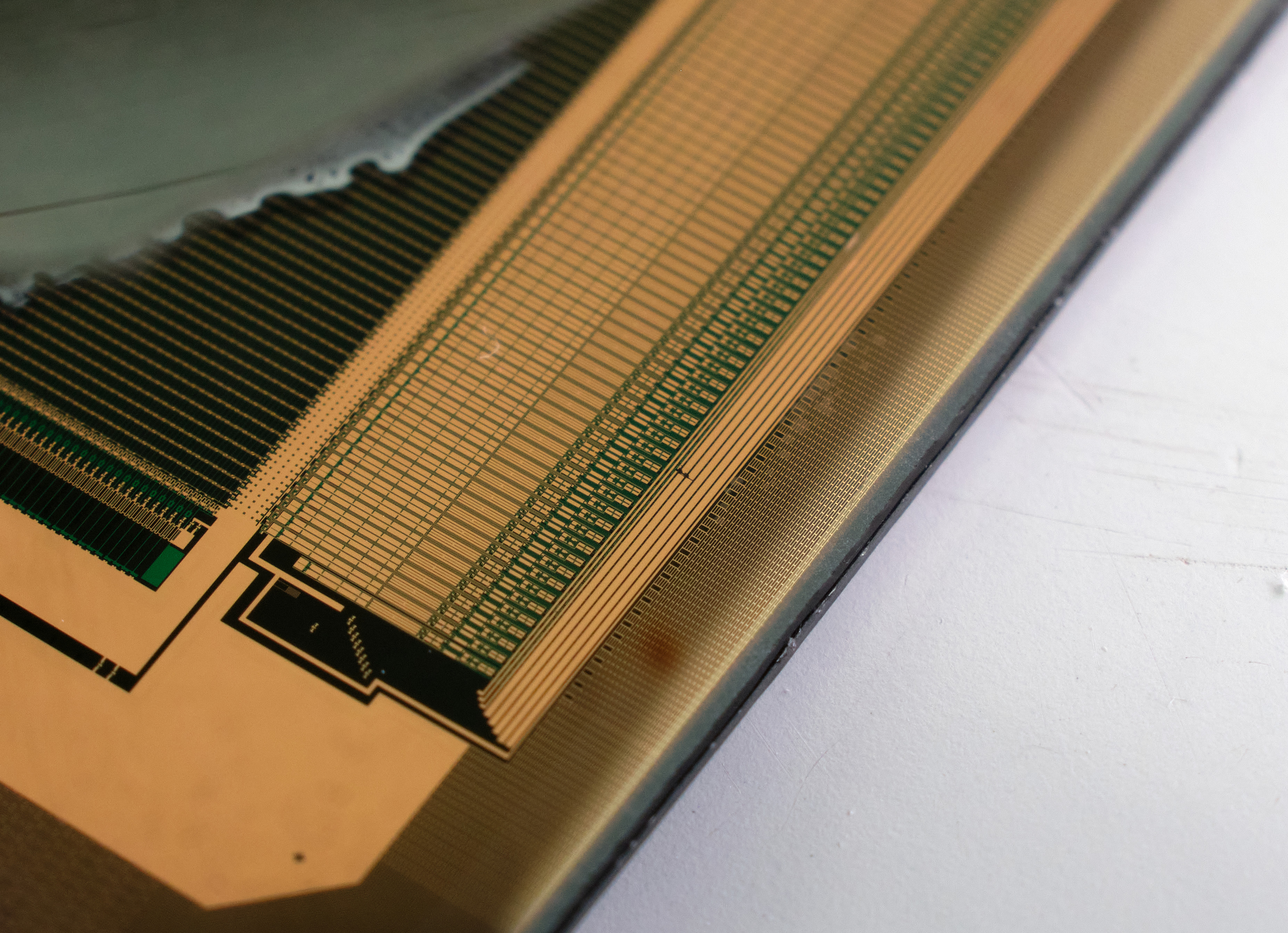
[The ware] was shot with a Fujifilm X-T30 using a 40-year-old Canon FD mount 50mm prime lens with a set of 10+16mm macro extension tubes. If you’re unfamiliar, extension tubes are basically a way of achieving macro photography without having a dedicated macro lens. They decrease the minimum focusing distance and increase the magnification of a lens according to the ratio between the length of the extension tube and the focal length of the lens, producing 1:1 magnification when the extension tube length equals the focal length. When using both the 10 and 16mm extension tubes together with the 18-55mm lens, my usable field of view is anywhere from 25-50mm wide depending on the focal length and focus distance with the subject ~0-20mm away from the lens, and with the 50mm prime, the field of view is 30-45mm wide with the subject 70-90mm away from the lens. When using extension tubes, I would highly recommend using manual focus, even though most extension tubes have the electrical connections to support autofocus – the autofocus algorithms on most cameras are just not tuned to work with extension tubes and often won’t focus at all or won’t produce as sharp of an image.
Thanks again to jackw01 for sharing this ware, and for sharing your know-how on photographing them!
Update Nov 5: the ware has been guessed as much as it can be (there is no expectation to guess the specific panel) so I thought I’d share these other images of the ware!
I think one of them might be be a great addition to the entries on TFTs or LCDs on Wikipedia.
I mentioned it to jackw01, and he said he’d be OK with sharing the photos using a Public Domain license and having them added — I’ll give that a try when I get a spare moment, if someone doesn’t get to it before I do!
My immediate instinct is a Josephson Junction array, as in precision voltage source, but there are some structures missing if that’s what it it. (Maybe off screen?)
Loops around the circuit are a coil antenna? I was originally thinking something like RFID tags, but that doesn’t seem feasible at IC scale. RFID tags are passively powered, so you want as efficient and large of an antenna as possible, eg one made out of real copper windings (not tiny on-IC windings).
The horizontal lines are pretty. I wonder if they’re gate-connected to the loop antenna or output-connected to the loop antenna. Perhaps they’re all identical, and you laser specific rows to one-time program in a key?
A 1D CCD array?
Based on the ability to image this with macro lenses and the structure, this is probably a MEMS device. I’m going to guess that it is a part of a MEMS accelerometer.
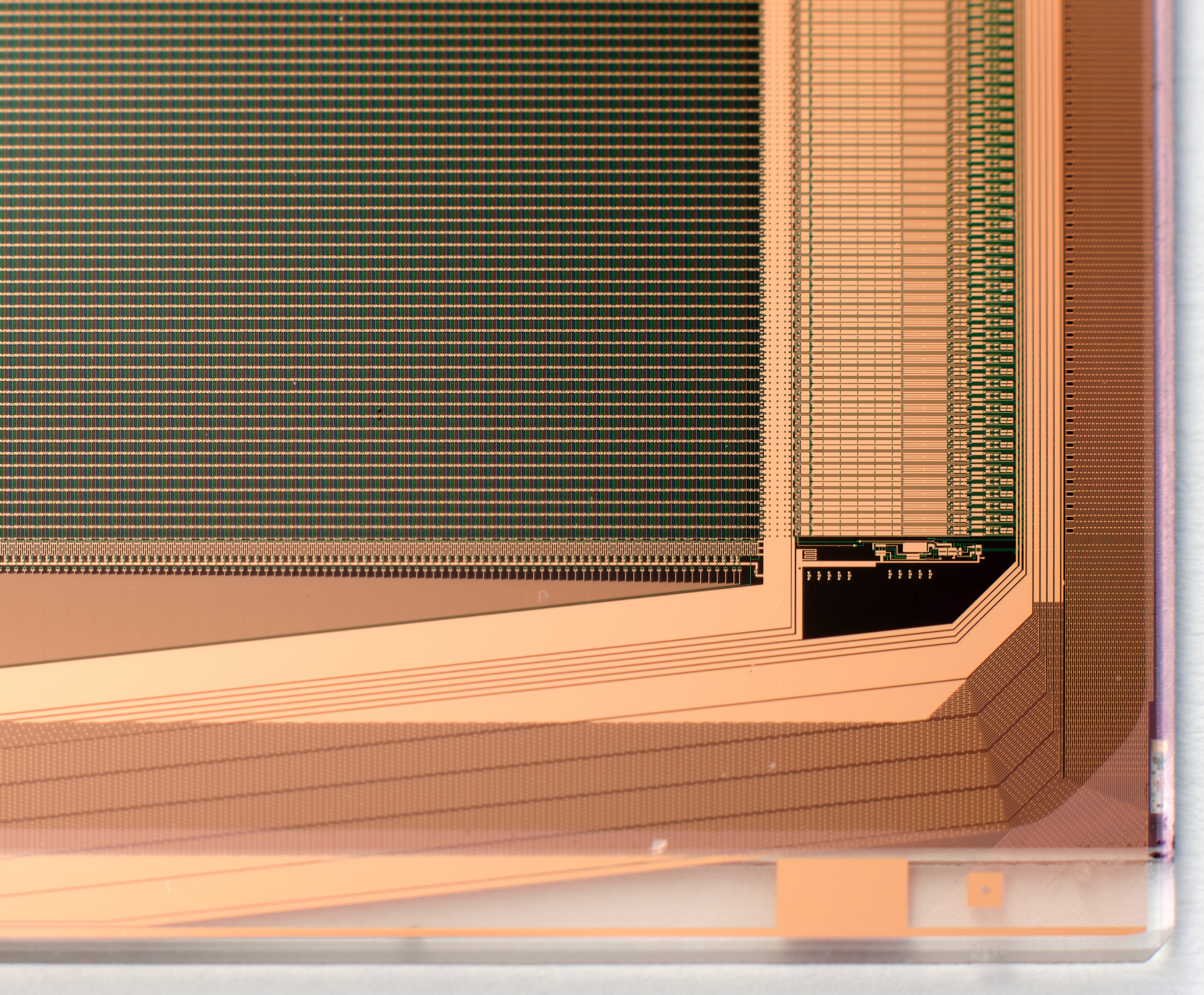
Could this be the edge of a TFT display?
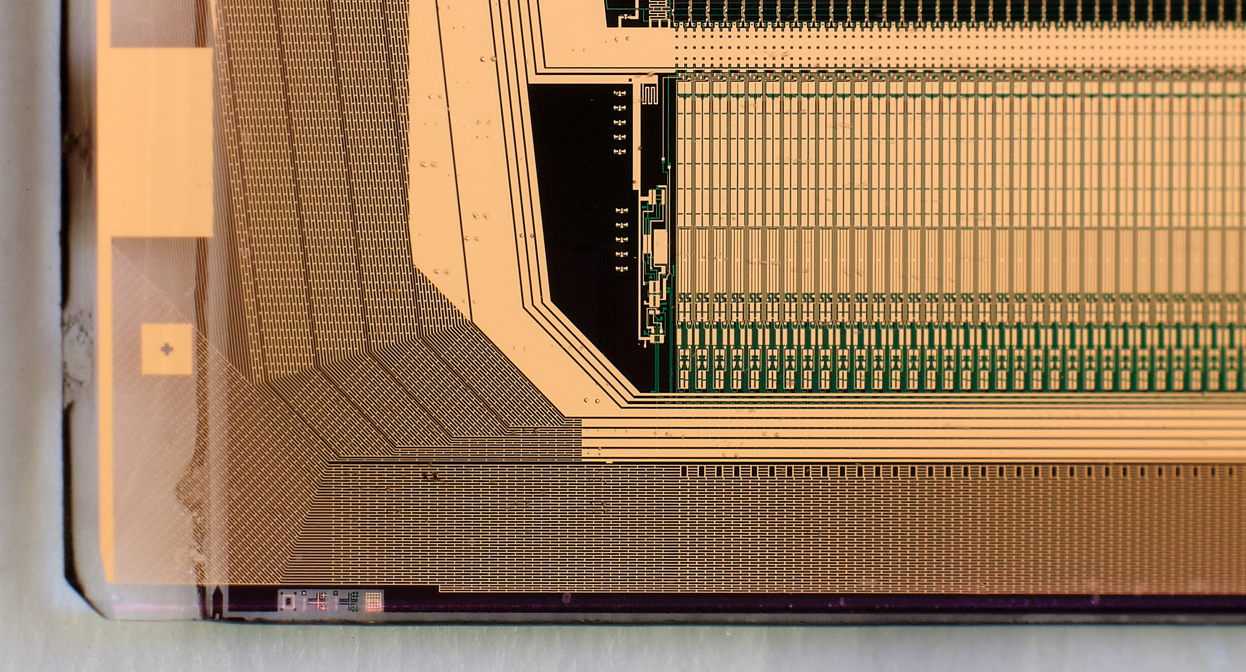
I think that’s a good guess, we’re looking at the column drivers
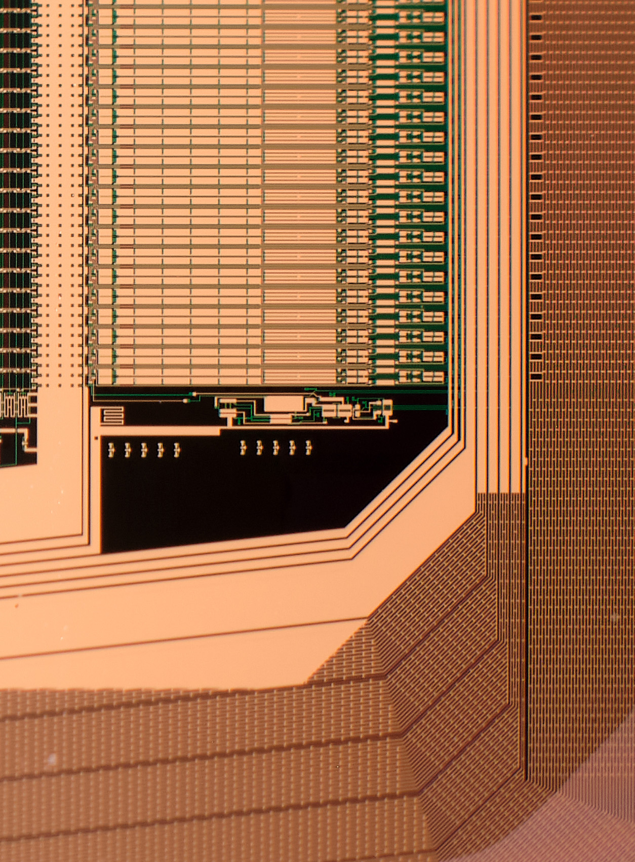
I’m pretty sure this is a TFT LCD display; you can even see the pixels with RGB filters on the left! It seems like there is one RGB column of dark pixels for some reason, then RGB going right to left. Given most displays use RGB column ordering, that makes me think we’re looking at the top left corner of a display, rotated 180 degrees. There’s also no clear indication of the 3 subpixels having separate column lines on the bottom of the photo, which makes me think this is a display where the columns are fed from the bottom and we’re looking at the top.
Most of the photo is taken up by the row drivers, which are just a big shift register or something like that, AIUI. This particular display seems to use fully on-glass circuitry for the row drivers.
Now, as for *what* TFT LCD display this is… I have no idea how I’d go identifying the specific model.
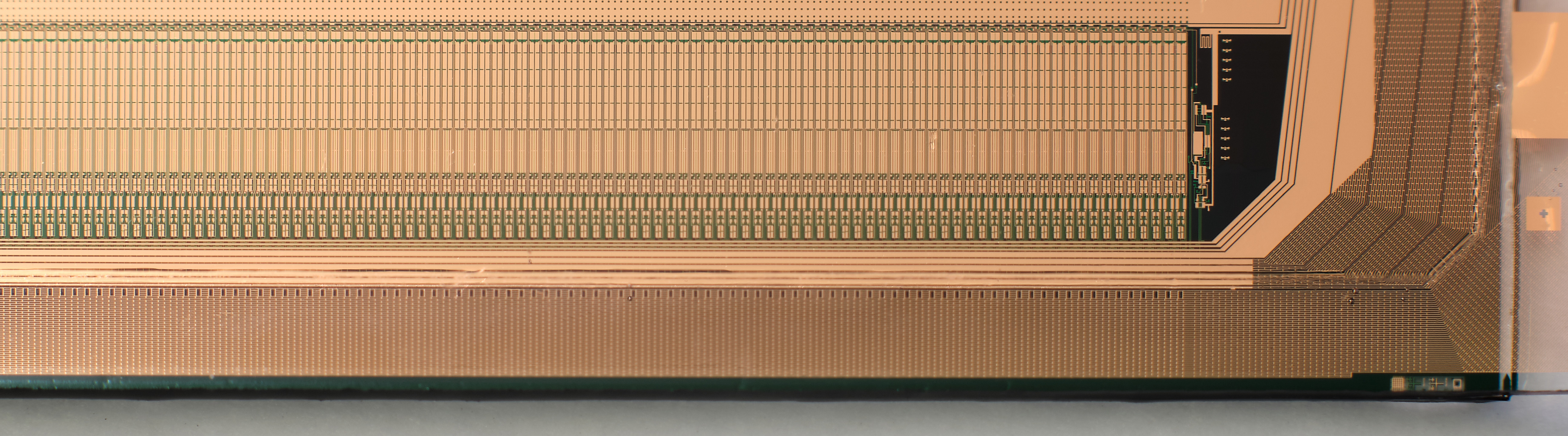
Well, that’s interesting. It seems there were column lines after all (the first one a bit shifted), but one for every two subpixels only. So this must be fed from both ends, with the top side column driver handling one column driver handling all the odd subpixels and bottom side driver handling all the even ones, or something like that.
Could those be row drivers after all and this could be one of those strangely ‘interlaced’ displays like the GameBoy used? Moto used on in the MotoG (first generation at least). The even/odd flickering is hard to get used to given their dissimilarity to modern progressive displays.
Nah, they’re definitely column drivers, in the context that the display is refreshed left to right, top to bottom. The row drivers are one big shift register, while the column drivers drive individual pixel data for each row and have a dedicated line per subpixel column from the driver IC (which is proper silicon).
I believe that “interlaced” stuff you mention isn’t actually due to the display being drawn in an interlaced fashion; rather it’s due to a quirk of LCDs where each pixel needs to have a zero net long term charge on it or else you get display persistence and eventually damage. One way to do this is to drive alternate rows at opposing polarity, flipping every frame, but if it’s not precisely balanced you end up with a visible interlacing effect. On many older TFTs, if the common voltage reference isn’t trimmed properly, you end up with that kind of interlacing effect for this reason.
Thanks for that explanation!