Thanks to Zack Weinberg for mailing me this device to take apart and share!
This entry was posted on Thursday, November 30th, 2023 at 11:16 pm and is filed under name that ware. You can follow any responses to this entry through the RSS 2.0 feed.
Both comments and pings are currently closed.
It’s the two missing LEDs that are really intriguing. Naively thought “that looks iPod touch-wheelish” but they have tact switches too. And … 6 out of 8 LEDs… Hmm.
Is it some kind of QI charging device? its got a ARM chip which seems over the top, but there is a decent slized cutout on the board, suggesting high voltage on the right and low on the left, and it looks like a MOSFET to switch the power to the “coil”.
It’s pretty wild this has been commercialized in an at home test for a reasonably low price. They utilized LAMP (loop mediated amplification).
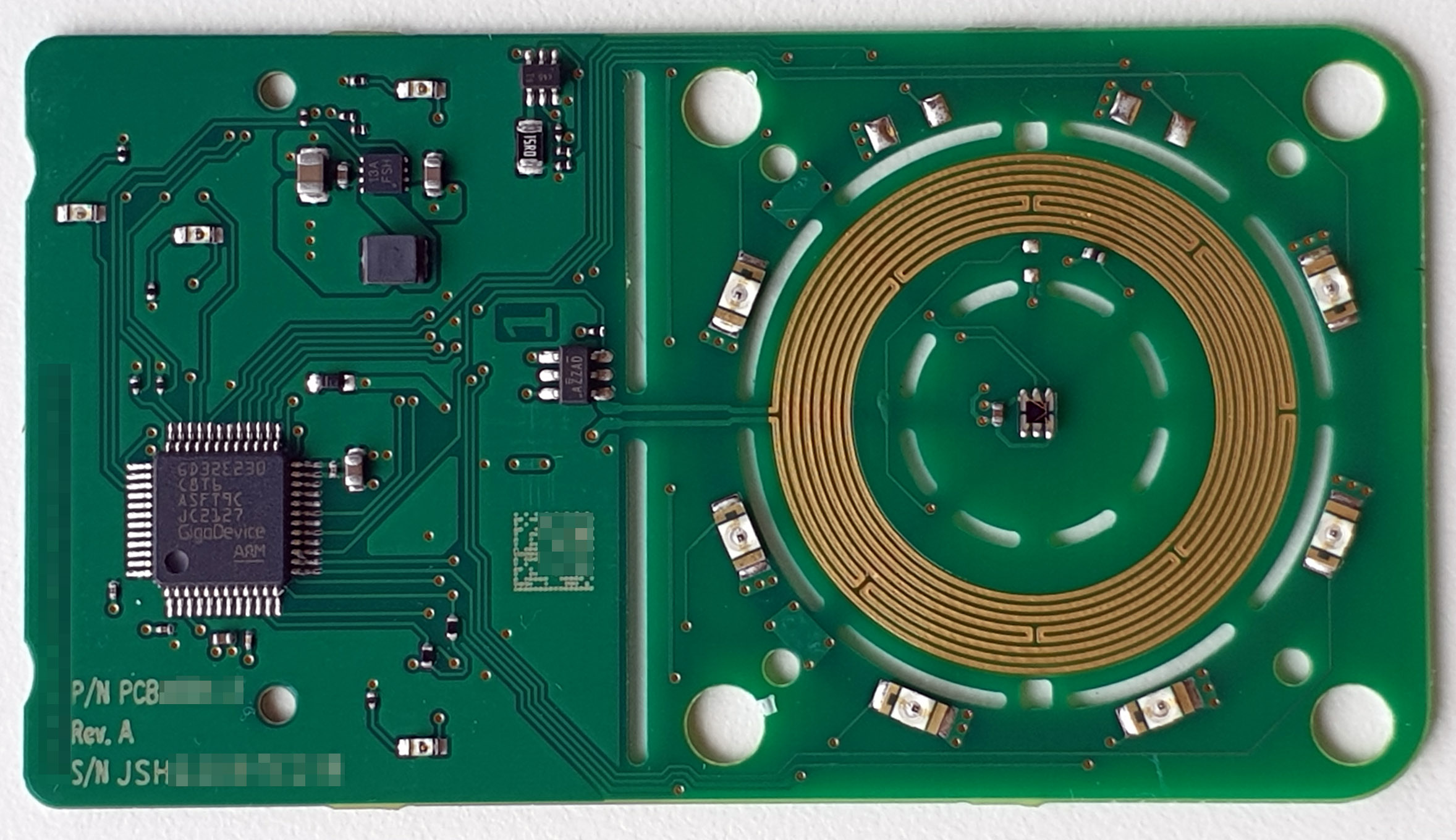
The ring of traces on the right is a heater with closed loop feedback to hit the fairly precise heat needed for the reaction to occur. The LEDs around the ring are used to illuminate the sample and check for fluorescence, which would indicate Covid DNA fragments in the sample.
Fascinating – I missed the LEDs on the non-test side at first, so I was very confused as to how the actual test works. Light pipes or something, incredible.
Identifying that surface mount component with the marking “AZZAD” would be helpful.
The central sensor(?) looks like a light sensor. “APDS-9306-065” (560NM AMBIENT sensor) looks a bit like it in terms of the leads and the visible bonding wires above a semiconductor die.
Another interesting question is how the device is powered. No visible connectors, and I don’t know why they’d put a connector on the reverse when they have a generous amount of space on the component side we’ve seen.
qi charger tester with discrete LED readout? and the light sensor is .. presence detect? doesn’t make much sense.
The particular type of wiggly trace looks like a heater, and in combination with the significant cutouts in the board to prevent heat transfer I’m pretty confident that’s the case.
The 8 distinctly controlled LEDs, and the small upward facing (?) sensor makes me think it heats a sample and performs some analysis using the reflections.
But I know nothing about that field, so it might just be a cup warmer with a lot of CPU for animating the LEDs :D
Is it some sort of AC electric field tester that points out the direction of it with the LEDs? Not only does it have what I’m guessing is an optical isolator on one of the antenna pins, but also has slots in the PCB which are usually to isolate AC from DC for safety reasons to prevent arcing.
The circular traces look to me like a heating. It’s kind of confirmed by the PCB cutouts that separate this heated area all around, and also from the left part of the board. Maybe an outdoor camera combined with the doorbell? The heating may serve to keep the lens free of moisture and haze.
The 6-pin transparent IC in the middle is certainly an optical device of some sort. It appears too primitive to be a camera, I’m assuming an ambient light sensor? However, Google picture search didn’t find any sensor where the bond wires go across the across the silicon, or the chip is segmented in the way it looks on the photo.
The LEDs could be IR or white light emitters to supply light for a camera. Logically that camera module would need to sit in the center of the circle but would then be on top of the optical IC. Which raises the question what the little 6-pin guy would be doing anyway? An optical chip always covered is no good.
Thoughts on the two missing LEDs at the top: if the entire camera assembly is covered by a glass dome, its top would be most exposed to the elements, i.e. would collect the most dust, snow, raindrops etc., so maybe that’s why this area isn’t illuminated, it would just create unwanted reflections from the stuff on top of the dome. Or, more trivially, the flat flex cable that might go to the camera module is routed across the top edge so these LEDs would be covered anyway?
Yeah, it’s a Lucira At-Home COVID Test. I’ve taken apart a few and noticed that they used STM32s in earlier batches and later switched to GigaDevice MCUs.
I cannot believe how wasteful a product this is. Single-use, seriously? It sure would have been possible to design this device based on exchangeable cartridges so at least the electronics could be used multiple times. It’s nuts how all of us are trying to be more sustainable and then this happens large-scale.
You think that’s large scale disposable – check out the Freestyle Libre blood glucose monitors. Similar electronics content and every one turns into a brick after 14 days. And they are sort of considered medical waste, so they usually go to landfill rather than the e-waste stream. I’d send a picture, but there are lotsa teardowns posted – it wouldn’t last an hour with our NTW group!
It’s a trade-off. Reusability isn’t free and is often a point of failure. A lot of reusable stuff still has a lot of waste as well in this space. It also reduces parallel throughput in cases where you need to test a lot of people in a short span. I think there are multiple valid solutions to this problem, even though some are more wasteful than others.
It’s the two missing LEDs that are really intriguing. Naively thought “that looks iPod touch-wheelish” but they have tact switches too. And … 6 out of 8 LEDs… Hmm.
Is it some kind of QI charging device? its got a ARM chip which seems over the top, but there is a decent slized cutout on the board, suggesting high voltage on the right and low on the left, and it looks like a MOSFET to switch the power to the “coil”.
Never thought I’d be able to answer one of these first!
It’s a Lucira at home Covid test. I first saw these in a teardown on twitter: https://twitter.com/bsa/status/1427438441814401039
It’s pretty wild this has been commercialized in an at home test for a reasonably low price. They utilized LAMP (loop mediated amplification).
The ring of traces on the right is a heater with closed loop feedback to hit the fairly precise heat needed for the reaction to occur. The LEDs around the ring are used to illuminate the sample and check for fluorescence, which would indicate Covid DNA fragments in the sample.
Pretty impressive test kit!
Fascinating – I missed the LEDs on the non-test side at first, so I was very confused as to how the actual test works. Light pipes or something, incredible.
Yes! The case which has been excluded has injection molded light pipes. Those light pipes point to the sample in the middle of the ring.
The little 6 lead IC in the middle of the ring is a color sensor that’s looking for a certain color change.
There is a teardown here: https://41j.com/blog/2021/12/inside-the-lucira-check-it-covid-19-test/
There is a fairly complex optical assembly with light pipes to direct the light from the LEDs through the fluid chambers to the photo sensor in the center.
Identifying that surface mount component with the marking “AZZAD” would be helpful.
The central sensor(?) looks like a light sensor. “APDS-9306-065” (560NM AMBIENT sensor) looks a bit like it in terms of the leads and the visible bonding wires above a semiconductor die.
Another interesting question is how the device is powered. No visible connectors, and I don’t know why they’d put a connector on the reverse when they have a generous amount of space on the component side we’ve seen.
qi charger tester with discrete LED readout? and the light sensor is .. presence detect? doesn’t make much sense.
I don’t think it’s an induction coil because it goes back and forth… Could be a heater but the supply traces don’t seem thick enough
iPod.
An iPod
Some kind of RFID reader, maybe?
The 6-pin device seems to control the operation of the coil. It looks more complex then just a MOSFET.
There’s also some kind of light or proximity sensor in the center of the coil.
My guess is a cheapo badge reader.
The particular type of wiggly trace looks like a heater, and in combination with the significant cutouts in the board to prevent heat transfer I’m pretty confident that’s the case.
The 8 distinctly controlled LEDs, and the small upward facing (?) sensor makes me think it heats a sample and performs some analysis using the reflections.
But I know nothing about that field, so it might just be a cup warmer with a lot of CPU for animating the LEDs :D
Is it some sort of AC electric field tester that points out the direction of it with the LEDs? Not only does it have what I’m guessing is an optical isolator on one of the antenna pins, but also has slots in the PCB which are usually to isolate AC from DC for safety reasons to prevent arcing.
The circular traces look to me like a heating. It’s kind of confirmed by the PCB cutouts that separate this heated area all around, and also from the left part of the board. Maybe an outdoor camera combined with the doorbell? The heating may serve to keep the lens free of moisture and haze.
The 6-pin transparent IC in the middle is certainly an optical device of some sort. It appears too primitive to be a camera, I’m assuming an ambient light sensor? However, Google picture search didn’t find any sensor where the bond wires go across the across the silicon, or the chip is segmented in the way it looks on the photo.
The LEDs could be IR or white light emitters to supply light for a camera. Logically that camera module would need to sit in the center of the circle but would then be on top of the optical IC. Which raises the question what the little 6-pin guy would be doing anyway? An optical chip always covered is no good.
Thoughts on the two missing LEDs at the top: if the entire camera assembly is covered by a glass dome, its top would be most exposed to the elements, i.e. would collect the most dust, snow, raindrops etc., so maybe that’s why this area isn’t illuminated, it would just create unwanted reflections from the stuff on top of the dome. Or, more trivially, the flat flex cable that might go to the camera module is routed across the top edge so these LEDs would be covered anyway?
Whatever, hope some of this makes sense.
Yeah, it’s a Lucira At-Home COVID Test. I’ve taken apart a few and noticed that they used STM32s in earlier batches and later switched to GigaDevice MCUs.
I cannot believe how wasteful a product this is. Single-use, seriously? It sure would have been possible to design this device based on exchangeable cartridges so at least the electronics could be used multiple times. It’s nuts how all of us are trying to be more sustainable and then this happens large-scale.
You think that’s large scale disposable – check out the Freestyle Libre blood glucose monitors. Similar electronics content and every one turns into a brick after 14 days. And they are sort of considered medical waste, so they usually go to landfill rather than the e-waste stream. I’d send a picture, but there are lotsa teardowns posted – it wouldn’t last an hour with our NTW group!
It’s a trade-off. Reusability isn’t free and is often a point of failure. A lot of reusable stuff still has a lot of waste as well in this space. It also reduces parallel throughput in cases where you need to test a lot of people in a short span. I think there are multiple valid solutions to this problem, even though some are more wasteful than others.