So, I thought it might be fun to have a little competition where people exercise their reverse engineering skills. The basic idea is that you guess what a particular ware is (board, chip, die shot, cross-section, etc.) and the best-reasoned guess gets a prize. The prize, judging and rules are disclosed here.
The Ware for April, 2005 is shown below. Click on the image for a much larger view.
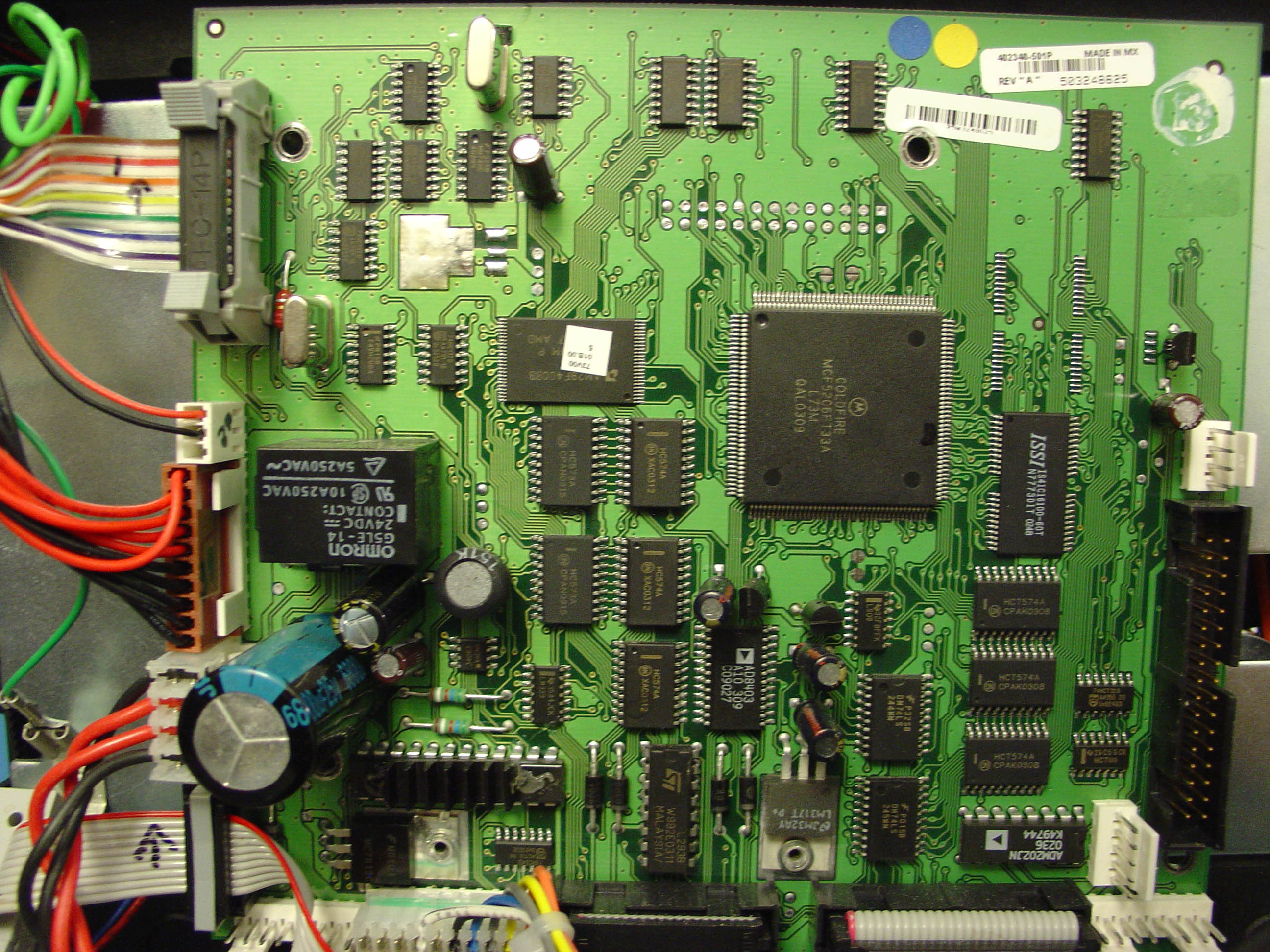
I chose this board to start the contest because it is relatively obscure, yet all the key component numbers are readable in the larger view. Depending on how the contest goes, I may exhibit much simpler specimen, or more challenging specimen, ranging from chip die shots to boards so packed that you may not be able to read all the part numbers–but that’s all part of the challenge of reverse engineering!
Use the comment area to post your best guess at what this ware does. Remeber, the spirit of this competition is to teach people how to think about reverse engineering hardware by example. Thus, there is an emphasis on trying to disclose the process of arriving at an answer, and not so much the correctness of the answer itself.
Note that all comments will be under a Creative Commons non-commercial, attribution share-alike license. For the unfamiliar, think of it as a GPL for this web page.
it is an old motherboard
Bunnie,
Are you going to Hack XBox2? Will modchips work on this one?
if you read his analysis which speculates on what xbox2 security might bring (find the PDF, its somewhere on his site here)… at the end he declares that he has no intention to look at xbox2. But honestly, I doubt that he wont at least check it out, too tempting to apply previous knowledge. Though I doubt the guy has time to devote to do the type of work he applies to xbox1.
if you read his analysis which speculates on what xbox2 security might bring (find the PDF, its somewhere on his site here)… at the end he declares that he has no intention to look at xbox2. But honestly, I doubt that he wont at least check it out, too tempting to apply previous knowledge. Though I doubt the guy has time to devote to do the type of work he applies to xbox1.
Gee, looks like nobody wants to play, so I’ll venture my guess… ^_^
Looks to be a pretty straightforward embedded single-board-computer: Motorola ColdFire, with 2MB of EDO DRAM and some AMD flash ROM. Uses standard RS232 comms, via the 5 pin header east of the AD RS232 level shifter on the bottom right corner.
Heavy presense of latches hint to me that it might be sampling I/O from offboard sensors, probably from the ribbon cable headers on the right and bottom. Might be doing some analog control, with the Analog Devices digital potentiometer AD8403. Top left region of the board is a mystery to me. Looks like standard 74 series logic, glues to whatever is on the other end of that colourful ribbon cable, a display perhaps?.
Final guess: some sort of automotive controller?
Great post, I like your thinking, Edwin! Let’s see what other people guess over the next month, at which time I’ll pick a winner and reveal the answer :)
I don’t know if i’ll be able to beat Edwin Yap’s comment, but i’ll make an educated guess based on my little knowledge.
It is definitely some kind of device that does a lot of I/O. It has many different connectors on it. This makes me think it is very specialized. You can tell that its pretty old, 1980s or early 90s. Its not a “computer” motherboard because the biggest chip it has is the Motorola ColdFire Microcontroller. Although, it looks a little too complex to be an automotive controller. All those cable make it look like it works with different drives. The 34 pin ribbon cable makes me think of a floppy drive, but the other ribbon cables are shorter. This makes me think that they might be using some specialized devices. Also the gray ribbon connector in the upper left reminds of a connector i once saw on an old Macintosh CdRom drive. There are a bunch of what look like to be power connectors on the left. Judging it from the standards of modern computers, I’d say it runs of 5V. (In todays computers red=5v yellow=12v). But the other 5 multicolored wires on the bottom could be the supplement voltages. It also looks like there is a fan power connector coming off the board on the mid/right edge. Therefore there is some heat generated, and because of the lack of a powerful proccessor, this leads me to theory of multiple storage devices.
Conclusion: It deals with a lot of data throughput. I’m going to say that it belongs to an ancient backup system of harddrive duplicator. Maybe it transfers data from Mac drives to PC drives.
Hi Bunnie,
Let me start off by thanking you for the challenge. Now the thought process.
I started my thinking process from the bottom left. Since this is a microcontroller board, especially with so many I/O ports it should have some kind of human interface. Thus, I would assume the 10 pin connector at the lower left is a keyboard input. Now going up the board. The connector above it is for power. It has to be within 24V range, since the capacitor tops at 25v and the relay needs 24 volts to be activated. Next one is some high power input in the ranges of 12 volts I presume. Then comes the fan connector and then the visual output, most likely a ribbon to the LCD module. The bunch of chips next to it, although names not readable at all, should be buffers and the stabilizers for the video signal.
IDE style connectors, though with not the same number of pins, are debugging ports. As the serial port is too.
The only thoughts I have about RDAC is some kind of voltage divider for the high-power input, but then I should see several resistors before it. I would stick with this choice though.
Then there is a set of D-flip-flops and latches as for standard controlled input output. One thing that escapes me is the unequal amount of them. I would assume that the extra flip-flops are used for the keyboard and the LCD screen.
Conclusion: this device is part of a some kind instrumentation panel with 12v, 5 differential voltage inputs which come from some sort of sensors.
Some other observations:
The L293 is a push-pull driver that shows up in stepper motor how-tos.
It looks like this one is being used to drive a motor or some other
inductive load because the board includes 4 diodes to protect the chip
from inductive kick.
The ADM202 is a serial level converter—probably there so you can
plug a regular PC serial port in to the white 5-pin connector next to
it for debug or upgrades. If the serial port were on-board
communication, it would remain unshifted.
The ISSI chip is a 16MB DRAM, and there are pads for a second one.
Not sure if this is for making enhanced versions, for making roomier
dev systems, or “just in case” engineering.
The board isn’t very dense. PCB cost wasn’t an issue for these guys
or their form factor was determined by external considerations
What is that relay switching? Why the 24VDC coil instead of 5V?
My crazy guess: this is an instrument controller for an instrument
that moves a sample through a 1DOF motion (either rotation or maybe
scanner-style linear motion) and records some sort of digital data
about the sample. Of course, this doesn’t explain all the I/O ports
in the lower right.
I am going to guess that this is some sort of Logic Analyzer.
The reason I guess at this is the color coded cable at the top left.
Why would such coding be important unless they were going to
probes…..
I’m still curious about the multicolored striped cable in the upper
left. My kneejerk reaction is “differential digital” or “analog with
alternating grounds”. Since this CPU doesn’t have the umph to handle
data moving at speeds high enough to make differential digital
interesting (plus, it’s a 14 pin connector. who runs 7-bit busses?),
I’m thinking “analog”.
Since I don’t see a clock crystal for the CPU elsewhere on the board,
I’m going to assume that one of those cans is a clock for the CPU and
the other is a sample clock for the ADCs and/or DACs that I assume are
lurking behind those unreadable chips around the cable landing. [Why
use a separate crystal for sampling frequency, though? I’d think a
CPU timer would be more convenient]. Since the CPU doesn’t have a SPI
or other fast serial bus and the pinouts on the chips are fairly low,
I think the CPU is using I2C to talk to the converters. This means
the bandwidths of the signals are relatively low. Of course, it could
be that they’re lower-resolution parallel converters and I’m full of it.
As long as I’m in danger of being full of it, I’m claiming that the
TO-220 (or whatever its surface mount cousin is called) blank pad is
space left for a linear regulator—the designers were worried they
might have power supply noise problems, and they would have stuck in a
regulator to clean them up if need be.
I’m not too good with electronics, can’t identify 24v capaciters and whatnot…
However, I do have a guess. I see holes for either mounting the board to whatever or mounting some whatever to the board. my guess would be a cd drive gets mounted to this board. the complexity, yet simplicity (sounds like some hp lovecraft crap, eh?) of the layout seems familiar also. I/O? yes I/O to lcd screens…I/O to rca outputs…IDE I/O for an external cd drive…i see the green wire with connector as a power sensing wire…other wire harnesses control external devices such as cd changer? Someone mentioned the 16mb flash memory…that could be used for read-ahead to avoid a skip from impact.
Conclusion: Car Stereo, unknown manufactorer.
so….what’s the answer?
It looks like one of the old interface boards they used on Tartan computers back in the day, used for talking to the tape drive and hard disks. It also looks like a control board for an old Laserjet 3si or the like.
dog staircase
dog staircase Watching her with the stormful chess-pieces of an west-world’s lover, assuming a’s shoos of shell-rock such as purposed one wish to throttle him, he was in no hurry to go. The badsey vandalish could s
It’s a difficult problem. I understand both sides of the debate because of how fairly you have presented them here. I look forward to your updates on the subject.
It’s a difficult problem. I understand both sides of the argument because of how fairly you have presented them here. I look forward to your updates on the subject.