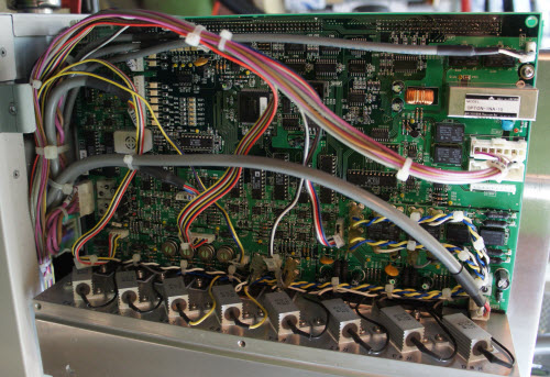
The Ware for April 2015 is shown below.
Have fun!
This entry was posted on Tuesday, April 28th, 2015 at 7:36 pm and is filed under name that ware. You can follow any responses to this entry through the RSS 2.0 feed.
Both comments and pings are currently closed.
Lots of power electronics, lots of digital to analogue to digital, lots of relays… true sine wave inverter? (wild guess).
I’m going to guess it’s a spectrophotometer, but can’t be more specific than that.
Wow, 8 20-watt wire-wound power resistors, a bunch of resistors, and lots of proper µc stuff too. I’m going to guess a battery controller or conditioner.
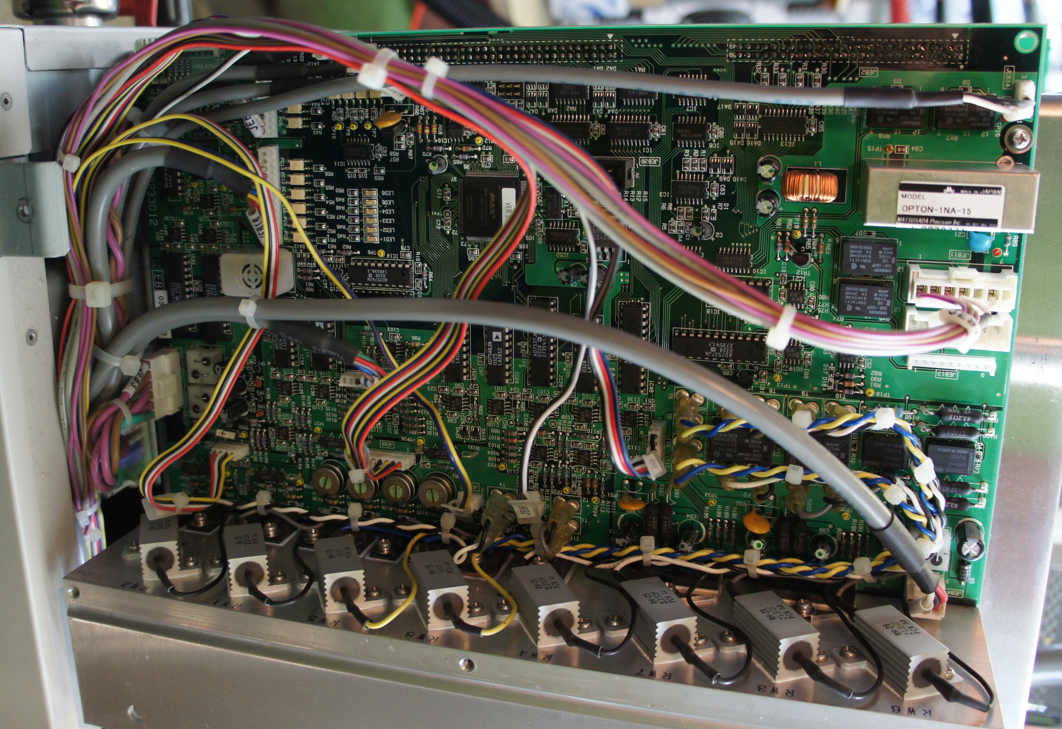
Matsusada Precision, hmm. Never heard of them but looks like a maker of power supplies of all sorts. With all the power resistors (mounted on a fairly serious heat sink, which looks like it should be a forced air one but I don’t see a fan) I’m going to guess some sort of electronic load or maybe a 4-quadrant power supply. From the construction it doesn’t really look like high-voltage gear.
Well, the Opton-1na-15 is an “ultra small low noise high voltage power supply for the photomultiplier.” That’s a start…
There are a handful of DACs, as well – the AD7548JN and AD7537(xx)s. There is one digital to analog converter, too (AD7574).
The Omron components on the right hand side of the photo are sensitive signal switching relays (http://www.omron.com/ecb/products/pdf/en-g6e.pdf).
A bunch of wire-wound power resistors line the bottom of the photo, and a little harder to see are a bunch of other components that require heat-sinking. They’re switches? Or drivers? Given that there are a bunch more DACs than there are ADCs, we might guess these are outputs, rather than inputs.
Along the top of the board (in the photo), there are two headers with 50(ish) pins apiece. So there’s a second board somewhere, at least.
The whole thing seems to be run by the Altera MAX device (FPGA? CPLD?).
So we’ve got a photomultiplier + ADC (a detector), isolation (via the sensitive relays), some reasonably high power output signals (resistors + heat-sinked chips along the bottom) and a processor to drive it all.
Wikipedia page on photomultipliers lists a few common applications: http://en.wikipedia.org/wiki/Photomultiplier#Typical_applications
I’m thinking either spectrophotometer, or one of the medical devices.
Looking more closely, there are a couple of parts labeled HM16S (one says 103G) near the top of the board. I can’t find the exact reference, but it’s probably not a coincidence that this lamp-cooling module has the same reference (HM16S): http://www.futurelightingsolutions.com/en/Technologies/Electromechanical/Thermal-Management/Heatsinks/Pages/3000014-HM16S-CALBL-001.aspx?ManufacturerName=AAVID-THERMALLOY&isFLS=true&IM=0
There is apparently a class of spectrophotometers that don’t use monochromatic light, but instead use a broad-frequency source and then do some complex analysis after the fact: http://en.wikipedia.org/wiki/Fourier_transform_infrared_spectroscopy Given the components on board, that’s my guess…
So, Fourier Transform IR Spectrophotometer?
MR16 is a ‘living room’ type of halogen lamp. The heatsink for building a LED variant of it also has an order code with ’16’ in it. The connector probably is not related.
I’m guessing it’s a programmable electric load.
Looks like it might be part of an elevator control system.
Omron reminds me of door controllers (security) that can open/close/lock/unlock doors.
I’m thinking a precision controlled photo welding device. Something that you may use to harden the epoxy of pipes or connections. Or, in the medical field for fillings in teeth.
The chassis is the key.
Based on the OPTON module on the upper right, it’s running at least one PMT and possibly eight – are the large resistors at the bottom current to voltage conversion ahead of per-PMT ADC? 50ohm is the usual output impedance of the (few) PMTs that I’ve seen.
Others have guessed a spectroscope, so I’ll strike in a different direction: a flow cytometer. The more advances flow cytometers can watch multiple fluorescence channels simultaneously, and there are some that do eight colours simultaneously.
s/advances/advanced/
PMTs normally emit pulses of a few million electrons each (when counting single photons), this is *not* something you’d convert to voltage by running it into a 12 Ohms power resistor :-). Having worked with them in the past, I can attest that it’s more like 10mV (into the typical 50 Ohms) for a few nanoseconds.
http://crop.unl.edu/schools/oscilloscope.html
(this one is actually a very strong signal)
Seem like there are PMT in used. I suspect this is a Xray machine.
But why is the beeper on this board? The variable resistors on the bottom look definitely old-school, a mismatch with the SMDs. As do the various test points and the LEDs on the board. Likely from something where the electronics is just a minor part of everything.
I think this ware is of a Japanese brand. The connectors point that way ans so does the OPTON module for which no English google hits are available.
I find the design kind of wonderfull – the top half is all surface mount, the bottom half is all through hole – it’s probably not a high-volume item – I’d guess this is rev 2 of something, keeping the analog bit that worked and was hard to get right and adding new stuff at the top – either that or we’re seeing the result of 2 engineers at war
Looking at the big resistors and all the heatsinked parts at the bottom I’d guess a constant current or current limited supply – the fact that they’re connected to relays might be auto-ranging stuff
What’s with the yellow balls on most of the test points?
they are plastic collars that keep a loop of wire oriented vertically from the board. the test points are not just pads- they can be clipped onto.
People seem to have overlooked the vacuum flange on the upper left of the picture. The large 1kV DC/DC converter makes me think of an acceleration voltage, as you might need in a mass spectrometer.
For light atoms such as Helium, a quadrupole mass spectrometer would need several MHz of few-100-Volts RF, which I don’t see, but maybe it’s using a static magnetic field?
A magnetic field could also explain the power transistors and high-power resistors and relays: You want to have a linear regulator to get low ripple. The relays might enable (or short out) series resistors which can dissipate part of the power to have less thermal stress on the transistors.
As a specialized kind of mass-spectrometer, it might as well be a helium leak tester, which is a self-contained unit with a multi-stage pump (typically roughing + high vacuum turbo) and a mass-spectrometer very sensitive to helium atoms. You’ll blow helium gas on the parts of your vacuum chamber you suspect to leak, and the device will detect the miniscule amounts of the noble gas reaching the pump. Because your vacuum system might be huge, there will also be beeper installed, so you don’t need to have the device in sight.
Signals coming from/going to the multi-pin connectors on the upper left (JEB18/…) seem to be isolated control signals (yellow/whiteish PCxx parts are optoisolators), would match what you expect from a single pumpstand controller (a few lines indicating roughing, failure, pressure thresholds reached, etc.).
I also wondered about a programmable load. And then about a 4 channel high power audio amp, with digital inputs – but the power resistors look too big. Also the high voltage inverter – what’s that about? could be for display stuff, but this looks too modern.
Also those heavy cables look like some big volts/amps are going to be coming off this board. Also there are a bunch of LEDs and a buzzer. And lots of AD/DA stuff. So, I’m going with some kind of physics-related test gear- perhaps for plasmas, something like that. But as I know jack about that field … that’s as good as I get.
You need to take part in a contest for one of the best sites on the internet. I am going to highly recommend this site!