The Ware for May 2015 is below.
Thanks to xobs for contributing this ware!
This entry was posted on Saturday, May 30th, 2015 at 10:18 pm and is filed under name that ware. You can follow any responses to this entry through the RSS 2.0 feed.
Both comments and pings are currently closed.


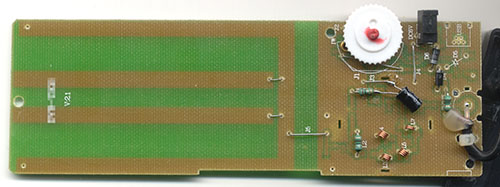
PCB antenna plus a bunch of powered discrete circuitry at the bottom, along with a footprint for what looks like a board-mount belling-lee/pal connector… amplified TV antenna?
I think you’re very close, I think it’s specifically a DVB-T antenna.
Plus, in the small image, you can actually *read* the word ‘DVB’ on the left hand side of the top picture.
The coils look like a filter section – my guess is a version of this DVB antenna with LTE filter. It has the scroll wheel, power, and usb connector in all the right places.
http://www.konigelectronic.com/en_us/television/dvb-t-terrestial/56020407
I think it’s this: http://www.amazon.co.uk/dp/B00KV9C7EW?psc=1
Could it be a (very old) model of a detector device for power lines, metal etc?
ok, i missed the USB connector :)
Apparently the USB would only be for power if it were installed. There are no ICs that talk USB, and only 2 pins have traces connected.
Could it be an aplifier for GSM/WiFi with external antenna on the other end of coax cable? Looks like there could be SMA connector instead of coax.
Given the tech it is cheap 80’s stuff. With USB. So … USB 0.1 protoype ;) but seriously it seems the four prongs are an antenna of some kind, theIC amplifies and after this a band filter follows. The pot and diodes are some form of attenuator / clipper. But why epoxy for something so shoddy?
Which doesn’t bring me to what it would be used for. Something handheld… some kind of metal detector perhaps, with the coax going into headphones of some sort. The useless USB option makes sense for that kind of gadget, as it will probably sell better with a USB connector (no software updates or PC connection, but the excuse is a power connector).
On the left side of the PCB, we have large traces that remind me of YAGI antennas, but they are different, so I would say it is a PCB antenna.
On the right side, we have a BNC cable directly soldered on the PCB, which hints at it either being an external antenna for some kind of radio device (TV/radio) or an oscilloscope.
On the upper side we have a power connector which is labeled DC6V, next to it is an unpopulated USB port, which has only the power-traces (the ones on the outside) routed, so the device runs on either 5 or 6 Volts.
The place where the BNC cable is soldered on looks like it was meant to be populated with a BNC connector instead.
The components C21 and D5 would be used to support the USB port are unpopulated too, and the pads for the USB connector look factory-new, so it does not look as if someone was short of a USB connector and unsoldered it from this device, I think this device is a variant of a device that has both 6V input and USB, but this variant comes intentionally without the USB port and without the BNC connector, perhaps to differentiate the price. Or perhaps it is a copied product, not genuine?
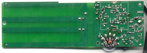
It seems there was a PCB shield desoldered from the 4 slots, which cannot be seen on the photos, the revealed components are mostly capacitors, so they are likely used for higher frequency (>1MHz) filtering, perhaps some are also used for power stabilisation. (Parts of the Pad on the top seems to have fallen off during the desoldering procedure)
The usage of SMA (solder mount adhesives) could indicate that the board could have been wave-soldered, where the adhesive makes sure that the components do not fall off.
It must have been a ‘what were they thinking’ antenna, with the wire bridges. Great find, Sourcerer!
IHMO the USB here would refer to the shortening of the Upper SideBand not to the Universal Serial Bus.
If it is a DVB antenna, there are no sidebands…
Following the copper this is an active antenna of some kind. The “sense”/antenna to the left is amplified by a MMIC amp then fed to a filter bank.
It appears there are more stop-band parts (L3/C5, L5/C8, L7/C10 for example) than pass band (L4/C7) in the filter, so it tries harder to avoid those frequencies, than letting the other frequencies through. This might be because the interfering frequencies are nearby and strong. And, as L3 and L7 are smaller they may indicate that the interfering frequency is higher than the frequency we want out from the unit.
The size of the coils for me also indicate that the system as a whole is well above the radio FM band, say, 200-800 MHz?
The potentiometer finally allows gradual shortening of the output amplitude, so it acts as a gain control. The pot double acts as the power switch with LED D7 indicating the “ON” position.
Finally, the coax is soldered instead of plugged into something that looks lika a common TV antenna jack from the silk screen print.
So my guess is this is an (indoor?/car?) active antenna för TV-reception, which filters out interfering band or bands above the TV band.
The MMIC pin-out matches many gain blocks (like this from Avago http://www.avagotech.com/docs/AV02-2244EN). The biasing thru L4 also indicates a basin block.
An air conditioning remote?