The “wäre” for July 2023 is shown below.
Thanks to zebonaut for submitting this ware. According to him, this was fished out of a dumpster in Germany, hence “wäre” (and yes, it’s a nonsense word, but I also think it’s cute). We had a little chuckle over the ware’s construction (or more precisely, the lack thereof). You could say, “they don’t build them like they used to” — could something like this pass certification in modern Germany? Well, it seemed to have at least passed the test of time, since it only recently found its way into a dumpster, and the rating label indicates a manufacturing date from the 14th week of 1996.
Update Aug 7
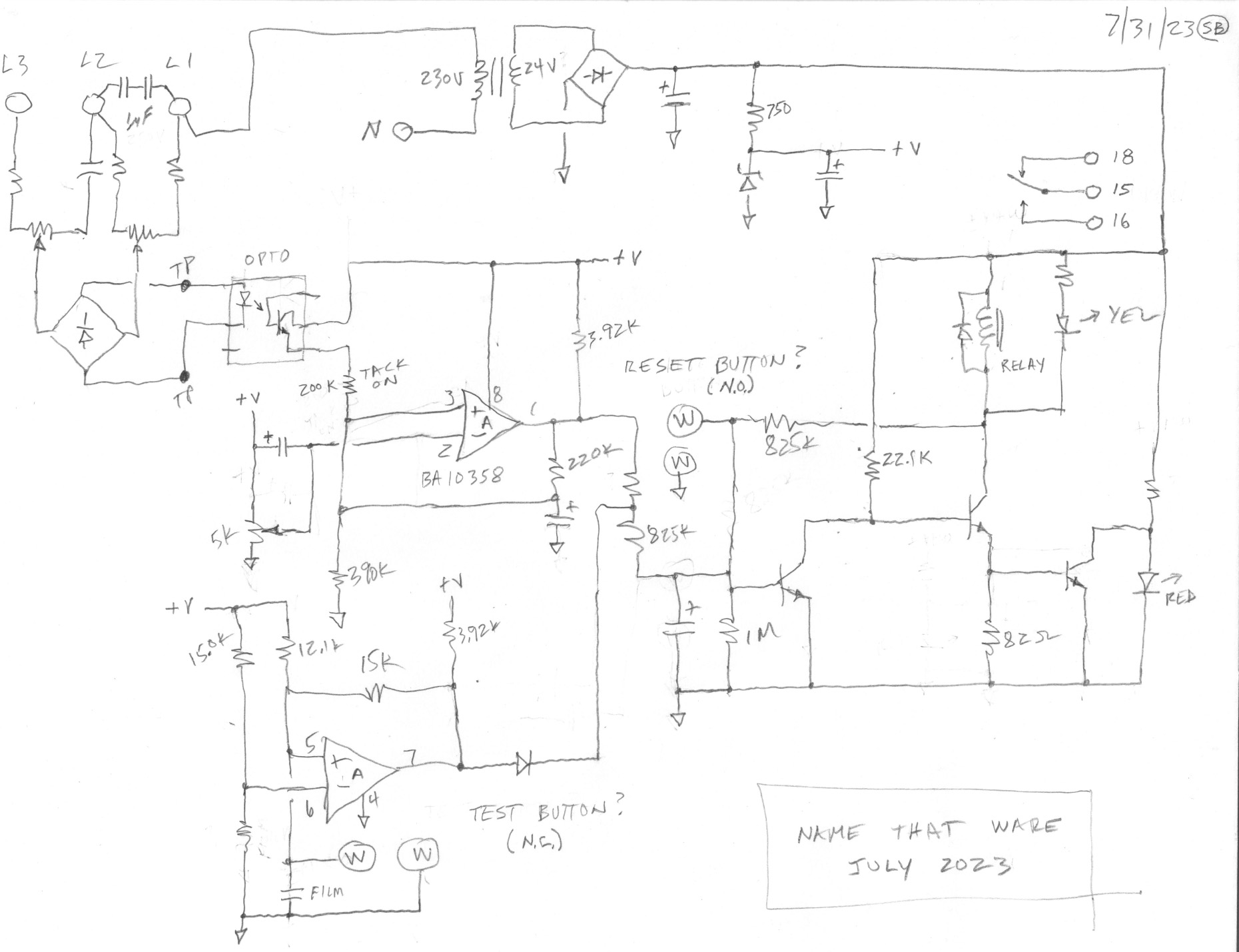
FETguy has contributed schematics for the ware, which he reverse engineered by hand:
A big thanks for contributing these! The spirit of Name that Ware is to inspire people to learn about electronics by taking things apart and observing their construction — and reverse engineering schematics is the asymptotic limit of that spirit!
Oddly enough, “wäre” is a perfectly normal German word. “Wenn ich kluger wäre, wäre ich glücklicher” -> “If I were smarter, I would be happier”
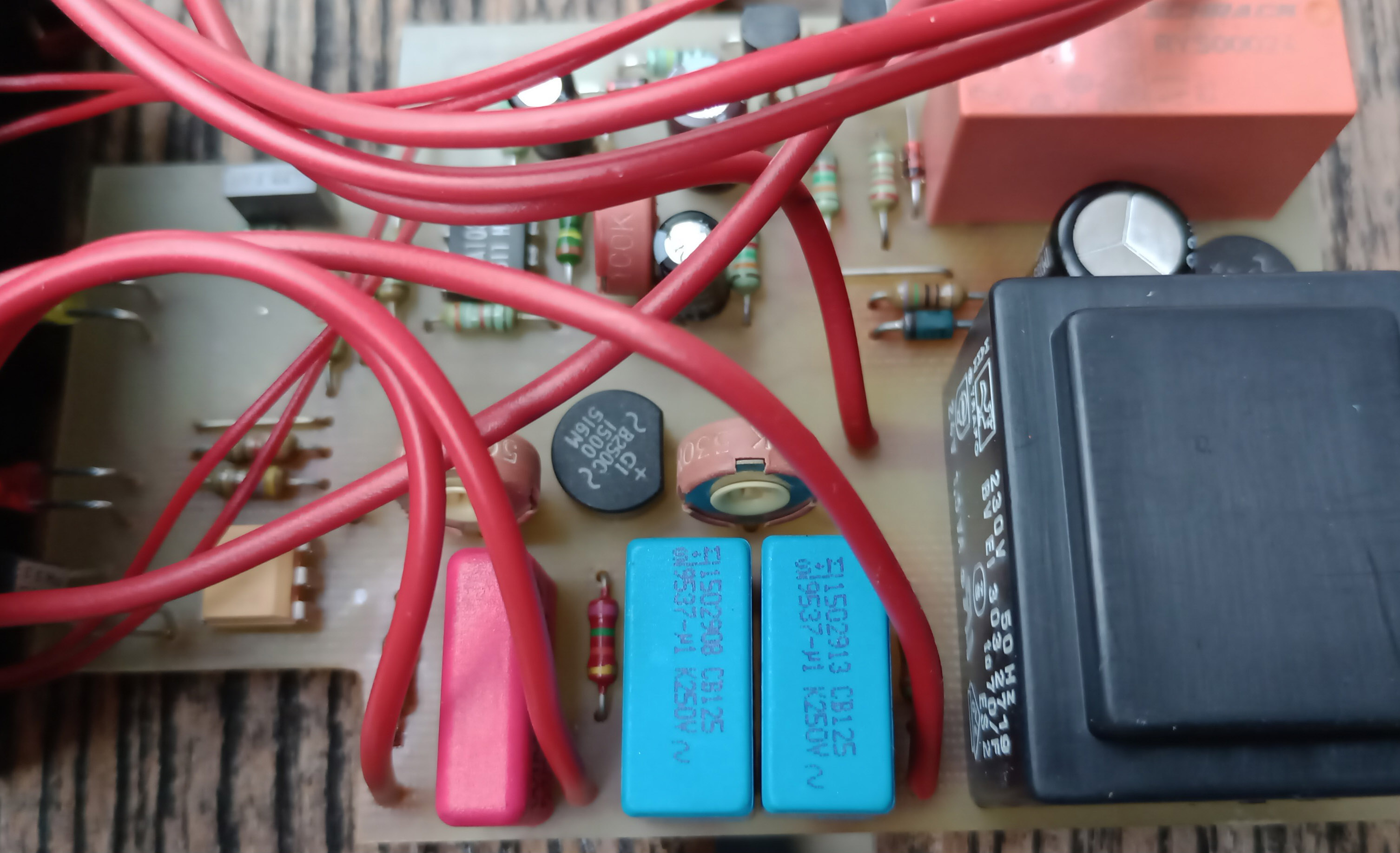
I’m going out on a wild guess here, but it looks like the insides of a monitoring relay or transducer (maybe phase sequence?) made by Crompton / Multitek, possibly rebranded by a German or other distributor. If the black plastic part on the left is part of the case, then it might have been awkwardly bodged into a different case from its original 55mm DIN rail mount case (the cutout on the left where the LEDs are would locate in the into the front panel giving clearance for the input/output terminals.
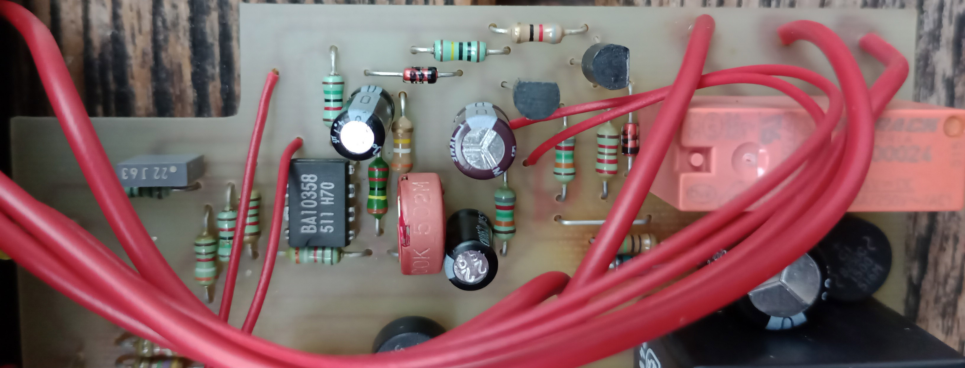
so… it has three-phase L1 L2 L3 inputs, AC coupled, which route through the trimmers and rectifier to an opto coupler. it then gets amplified (BA10358 is what it sounds like) somehow (I’m too lazy to trace out the schematics) and controls a relay. so it detects the phase (as adjusted by the trim pots) and acts on that.
my guess is this monitors the phase imbalance in a 3-phase AC system (aka normal domestic power here in Germany) and switches in or out a capacitor bank to compensate.
or all that circuitry is meant simply to have the relay switch during the zero crossing of a particular phase. this being a German ware, having something this massively overengineered does feel right… (IMHO German engineering isn’t any good. German manufacturing is simply good enough to actually build the overly complicated crap our engineers design.)
I obviously thought “power supply” initially because of the mains transformer. but the circuitry clearly does more.
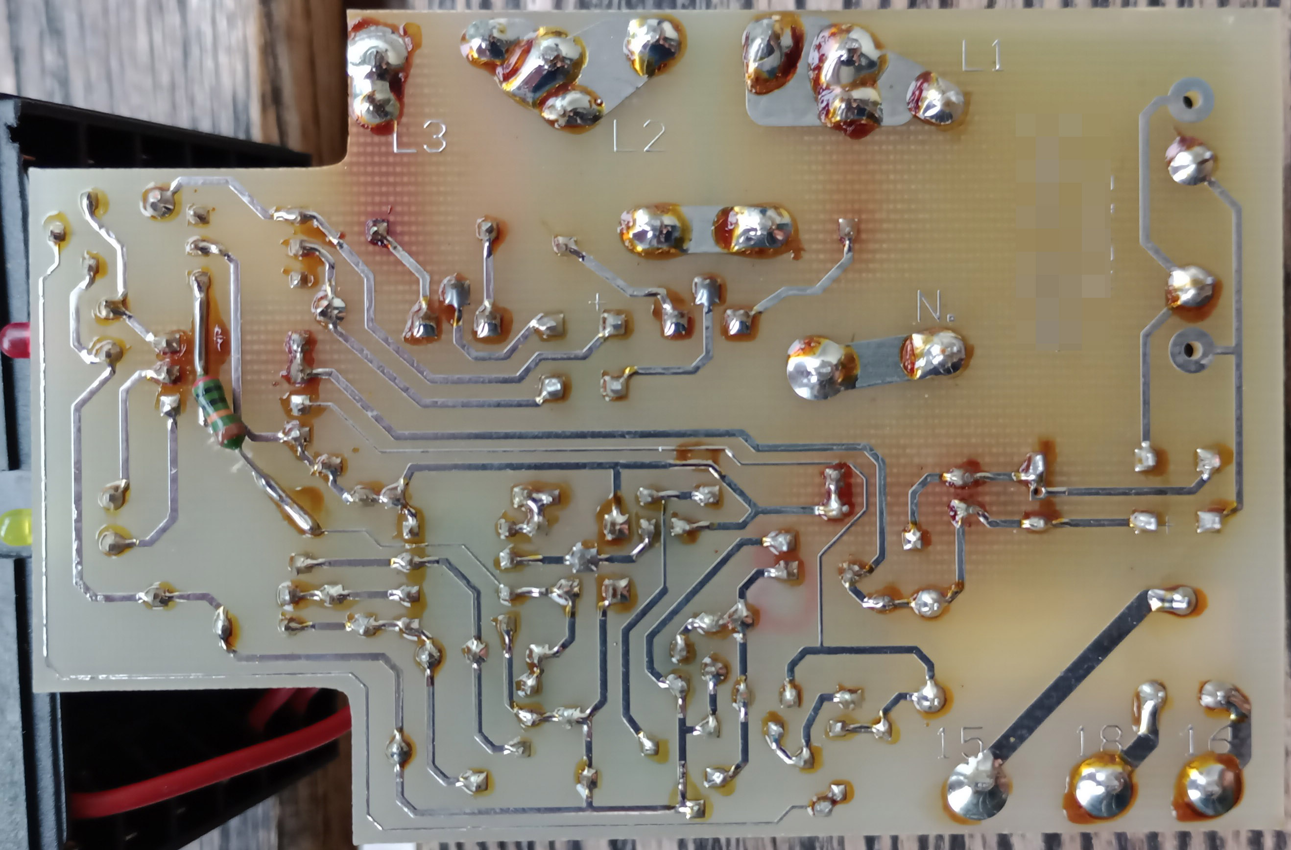
just realized there’s a glimpse of the front panel in one of the shots. whatever it does, given the PCB shape this is almost certainly meant to be mounted to a DIN rail in a fuse box.
omg wait. 2 LEDs, 2 random pairs of wires leading to the front panel… please please tell me this thing isn’t an RCD! it would make sense: phase imbalance means current is leaking elsewhere, so the RCD needs to trip (the relay). the LEDs would be to indicate state, and the buttons are test and reset. the relay would then need to trip a larger 3-phase relay, though… that’s the part that doesn’t entirely fit.
I do not approve of that construction for a safety-critical device… that heat darkening of the board doesn’t inspire confidence.
as said, 3-phase AC is the normal domestic power in Germany, so 3-phase RCDs are found in many residential fuse boxes.
I wonder if it this is a ripple control receiver? Some German utilities use ripple control for demand management and tariff selection – i.e. cheaper nightly rates for heating, etc.
They inject harmonics in the 50hz wave to remotely trigger load switches, especially for so-called storage ovens.
https://de.wikipedia.org/wiki/Rundsteuertechnik // https://en.wikipedia.org/wiki/Load_management#Ripple_control
I think it is just a phase loss/imbalance detector. It looks like the input circuitry just senses voltage differences between the 3 phases and two trimpots adjust that. That signal gets rectified and applied to the input of the optocoupler. Maybe the rest of the circuitry is delay, set/reset, etc.
First thought it might be this: https://eu.mouser.com/ProductDetail/Carlo-Gavazzi/DPA71DM48
But then the relay certainly can’t switch three phases at a time, rather appears to select one out of two. I imagine this might be some kind of automatic phase selector that detects the ideal phase (out of two) and switches the relay (and thereby the 1-phase consumer) to it. Couldn’t find any such product though, let a lone with a black front panel…
I went ahead and made a schematic of the board. Recreational reverse engineering. I would be happy to scan and share it, but have no ready way to post it anywhere. Send it to bunnie? Anyway, I have several observations; here are a few:
It is indeed a phase loss detector The relay is normally on, and phase loss causes it to release and stay released by latching of the transistors.
The 4 small red wires are a mystery, but two of them, if shorted, cause the fault latch to be cleared, so I suspect they go to a reset button. The other two go to a second fault input, so they may be another detector of some kind, but may also go to a test button; if so, that button would be normally closed, which would give fail safe design against broken wires.
A clever point is that you can see that the power transformer feeds from the L1 terminal to Neutral. So what happens if you lose the L1 phase? Answer: it powers from L2 via the two blue film caps (in series for safety). So it stays live and working through loss of any one phase.
Anyway, I think the design of this ware is better than the construction style would indicate.
Sure, if you email it over to me I’ll add it to the post! I think also for that level of effort you would basically win the competition, I’ve never had anyone submit a schematic as an answer before — but that qualifies as a definitive answer in the spirit of the competition.
Oww, I like this new rule! Time to fire up KiCad at the end of each month. :)
Could the four mystery red wires be links to other boards which may be operating on different phases? Do that they enable/disable this board under the right conditions?
I know zero about these devices, but I’m just extrapolating from this handling two phases when most commercial power is three phases.
A schematic! More than a dumpster find could ever have dreamed about! Amazing, especially because I decided to take pictures because the little thing looked like just very few were ever built and it had not received any fame at all, ever. If the transistors had feelings, they would certainly jump out of the board in pure joy.