The Ware for October 2023 is shown below.

Thanks to JeffreyO for contributing this ware!
This entry was posted on Tuesday, October 31st, 2023 at 2:25 am and is filed under name that ware. You can follow any responses to this entry through the RSS 2.0 feed.
Both comments and pings are currently closed.
The things in the lower left hand side are clearly Halloween pumpkins but I can’t identify any other trick or treat features.
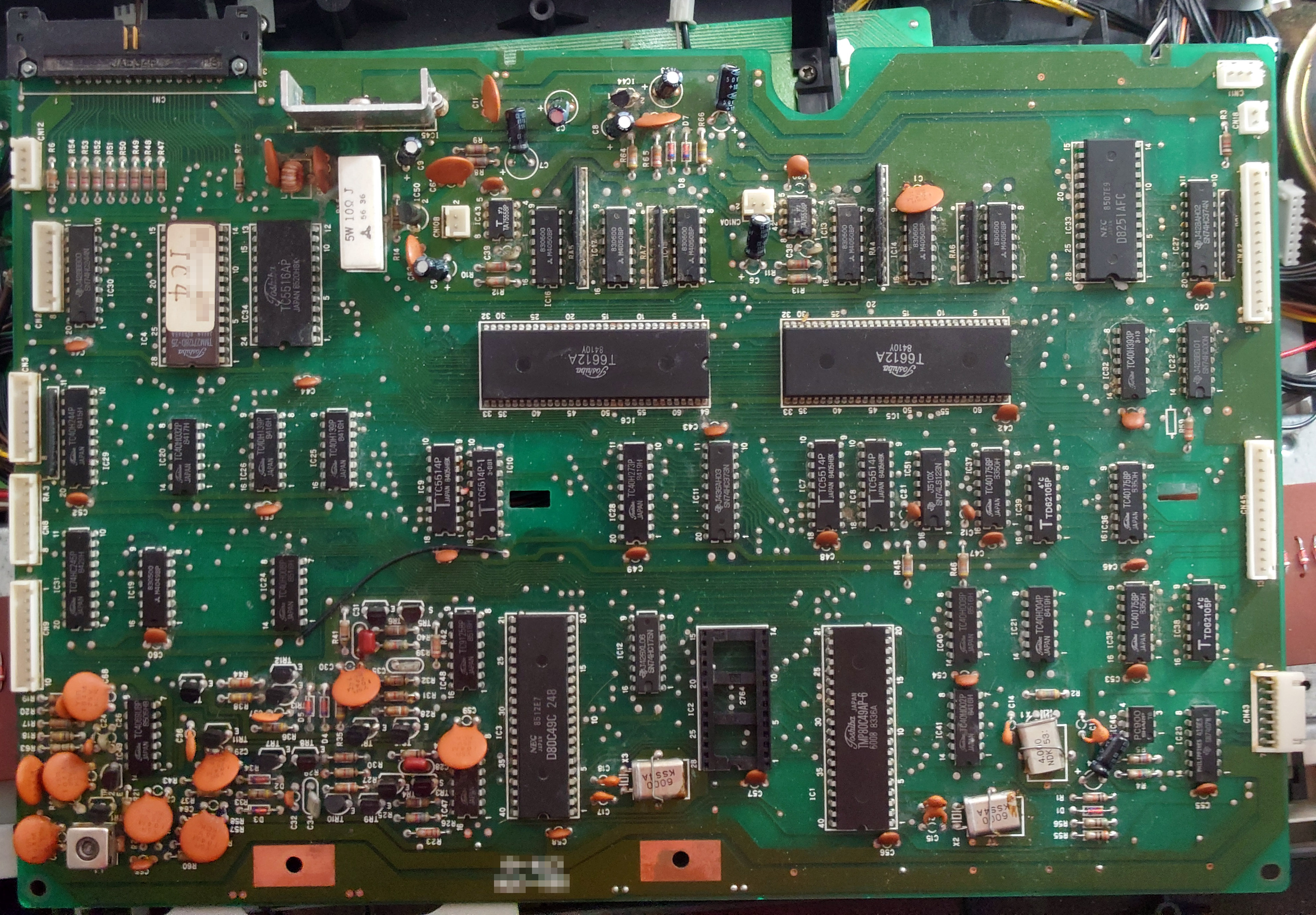
That screams floppy drive controller to me. As in the board that is part of tha hard drive and interfaces to a PC and to the mechanisms/motors/heads in the floppy drive. From the size, it’s for an 8″ drive.
Threre is a lot of duplication of parts. For example, those T6612A 64pin DIPs are clearly processors of some kind. They’re surrounded with the normal variety of memory and some I/O. The D80C49C is a TLCS-48C based 8 bit micro. As is the TMP80C49AP-6–just with more I/O. There’s a missing EPROM between them, not sure what role that plays, but it may act as a decoder for the signal that seems to be coming/going to the lower left of the board where the analog circuitry is located.
The D8251AFC is a USART which is an odd thing to see on a board that I think is a floppy controller. Given this board was built in the mid 80’s from the date codes, it’s highly overdesigned for a simple floppy controller. Also, it’s completely missing all the motor drive circuitry I would expect to find. There must be a companion board to this that does the motor power control at the very least.
I would guess this board is made by Toshiba given all the parts on it being mostly Toshiba, but it most certainly was designed by a Japanese company because of the origin of all the parts appearing to be Japanese. I count only 5 chips on that board not of Japanese origin and they’re all TI. Oddly, none of those seem to be anything fancy or TI exclusive, so Japanese versios should have been available.
Very curious board. I’d love to see the other side. The screw pattern and the various cutouts are also curious. Oh, I almost forgot to mention the big reason I assume floppy–the 34 pin connector on the upper left says HD/FD, but the low frequency of all the XTALS in the board says “not HD”.
Good luck!
It is a musical keyboard with MIDI, speaker(s), and what seems to be a disk drive. I searched for 15 or 20 minutes but I can’t find this particular unit. I thought it was odd that the speakers were included because the disc drive. It seems to be low end. I think this unit would be towards the mid to late 80s. I have many many keyboards and racks most of them are from the 70s and 80s.
-Cary
Oh wow, I hadn’t even considered that but I think you are 100% spot-on. Things to support it, from more obvious to less obvious:
1. The USARTs mentioned by willmore would be necessary for MIDI
2. The edge of what’s clearly a speaker in the top-right corner of the photo, behind the board
3. The large plastic frame with sheet metal reinforcement behind the keyboard matches other 80’s-ish keyboards I’ve seen inside
4. The single-sided board visible at the lower-right, with a few diodes lined up in a row, is probably what extends the full width of the keyboard and holds the diode matrix used for row/column scanning of the (musical) keys by the controller
(Also meant to mention that you can see the keyboard diode-matrix board continuing with more diodes through the lower-left corner of the image, so seeing a board with diodes isn’t just a one-off fluke)
I completely agree with you. I withdraw my floppy controller idea. Yours fits the board way better and explains all the stuff my theory didn’t. It also explains why there seem to be way too many processors on there–each one handles one specific realtime task–maybe in stereo even. It also explains why a microcontroller would have an EPROM next to it–when they clearly don’t need them to run. It might be some kind of sample lookup table or melody/rhythm table kind of thing like they use to customize a single design into a dozen variants (Oh, you want the Salsa rhythms? You need the special Salsa version of the keyboard… *dude in factory plugs in Salsa EPROM and puts a different sticker on the case and box*)
I had hoped based on the chips in this that it would be something like a pc-98 or an msx2, since they are all Japanese chips from 1984-1985 and there is a JAE 34 pin header for a 3.5″ floppy drive. But the toshiba MSXs from this era don’t match — there should be a Z80 on there somewhere, nor does it match the floppy controller in the nec pc98 with a 3.5″ from that time period. Toshiba’s early T1100/T2100/T3100 dos laptops are also out.
Based on the d80c49c showing up on synth part websites, my guess is that this is from either a korg or roland sampler manufactured in mid-late 1985.
A keyboard would be my guess. I’ve seen teardowns of them and most use the single-row connectors like the ones around the board. And most keyboards were from Japanese brands. A dual-processor setup for effects might make sense in the 80s to early 90s.
Pretty sure it’s an electronic keyboard / synth, maybe a Roland, probably around 1985?
Confused on the large 64pin DIP Toshiba T6612A parts – can’t find any info on those even though they’re very prominent. 2 different 80C49 microcontrollers! Almost everything is Japanese excepting for a couple of TI parts, so that says almost certainly Japanese design / manufacture at that time.
Even the 74 series TI parts were made in Japan based on looking up the part numbers.
A few observations:
The connector in the upper left looks more like a parallel interface (8 termination resistors), rather than a floppy (which is essentially high speed serial). It has too many pins in use to be a Centronics-style interface. It’s not a PC-style floppy interface, even though it has 34 pins, as the PC interface has odd pins grounded, and this has both rows in use. It’s right near RAM/ROM so maybe it’s a memory cartridge interface, or maybe it takes the system bus to another board?
Bottom left looks like RF, not AF. There’s an RF PLL chip as well – TC9125BP – min freq 200kHz, max 10-20Mhz.
The D8251AFC UART doesn’t seem to have enough supporting circuitry for MIDI (op-amps, resistors?), although that could be on another board.
Given the lack of references to them on the net, the big T6612A may be mask-programmed micros with a customer-specific part number, but why two identical ones (i.e. same programming)? Quite a bit of identical support circuity around them, too – TA75558PA op-amp on both (something analogue), CN10A/CN10B connector naming, a couple of RAM chips each (2 x TC5514P – 1K x 4 bit SRAM).
No sign of DAC (or ADC), discrete or otherwise – possibly inside T6612A?
Surprisingly little glue logic – mostly buffers, drivers and inverters – maybe inside T6612A?
Only 16kB of ROM (27128), 2kB RAM (TC5516AP) – rather modest ROM if this is a synth.
The three 4050s and the 12 and 8 pin SIP resistors above each T6612A could be discrete DACs.
More thoughts…
It sure looks like a synth or keyboard of some type, although the lack of AF filtering and an RF PLL is unexpected and hard to explain. It’s also not near the other analogue parts.
Black plastic case, speaker on left just above keyboard, mono amp – that limits it somewhat – likely some sort of consumer-grade electronic piano, rather than serious synth, but still moderately expensive.
I did wonder if the 34 pin connector was an MSX bus, but the pinout is all wrong (MSX is also a 50 pin edge connector) – not impossible but unlikely.
64-pin Shrink DIP is unusual – I looked at what chips Toshiba was making in 64 pin SDIP – they did have a range of Z80 ISA microcontrollers that featured ADC and DAC.
I looked at contemporary Japanese synths without finding anything similar. Yamaha, Roland, Korg had way more analogue stuff in their digital synths, branded their ASICs, were already using QFP packages, and nearly always had a coin cell. Casio’s PCB are distinctive and quite different from anyone elses. I looked at more obscure options also, such as Kawai, Toshiba, Panasonic/Technics without finding anything likely.
The number of Toshiba chips is suggestive of a Toshiba product or design/manufacture by Toshiba for somebody else. As noted above, the other large Japanese companies tended to brand their ASICs.
16kB of ROM isn’t much sample memory. Second ROM socket appears to be connected to one of the 80C49’s, and is only 8kB, so probably not sample memory?
Argument for it being a synth: you can see on the bottom right a brown board with a lot of parallel diodes, which are usually found for the keyboard switches PCBs I agree with the others saying that it seems very simple to be a professional chip, could it maybe be some consumer stuff? The absence of Y-marked chips suggests not Yamaha, I think not Roland either.
Toshiba HX-MU901
nope i take that answer back … its not, board is to complicated for the mu901
second try: a casio keyboard, still trying to find out the type
The board looks similar to Yamaha/Korg. Yamaha was also a supplier to Korg around that time so it could have been either one in my opinion.
My best guess would be the KORG SAS-20. The brown board in the background and metal frame under it looks a lot like the key pcb and mounting bracket on the Korg. However, the circuitry doesn’t match the pcb in the service manual that is available online. That one has a 64K eeprom, as opposed to the 128K in the image. It looked for a second that the 34 pin connector was for the SAS cartridge for the keyboard, but unfortunately the cartridge only has 24 pins.
Possibly a later generation of that keyboard. But more likely another product from Korg that I haven’t found.