The ware for March 2024 is shown below.
This fine ware is courtesy of KE5FX. Really fascinating stuff, thanks for the contribution!
The ware for March 2024 is shown below.
This fine ware is courtesy of KE5FX. Really fascinating stuff, thanks for the contribution!
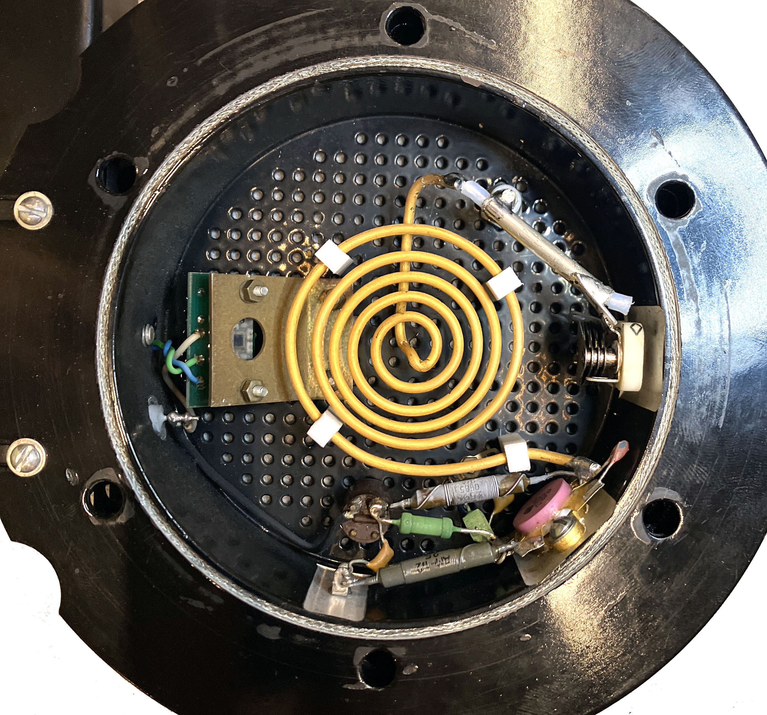
Could the ware in the first picture be a slightly modernized version of a spark gap receiver? Searching around the internet I see that spark gap receivers traditionally include a neon bulb. Maybe the neon tube in this ware is used in a similar circuit, with the photo diode to its left translating the flicker of the tube into an electrical signal.
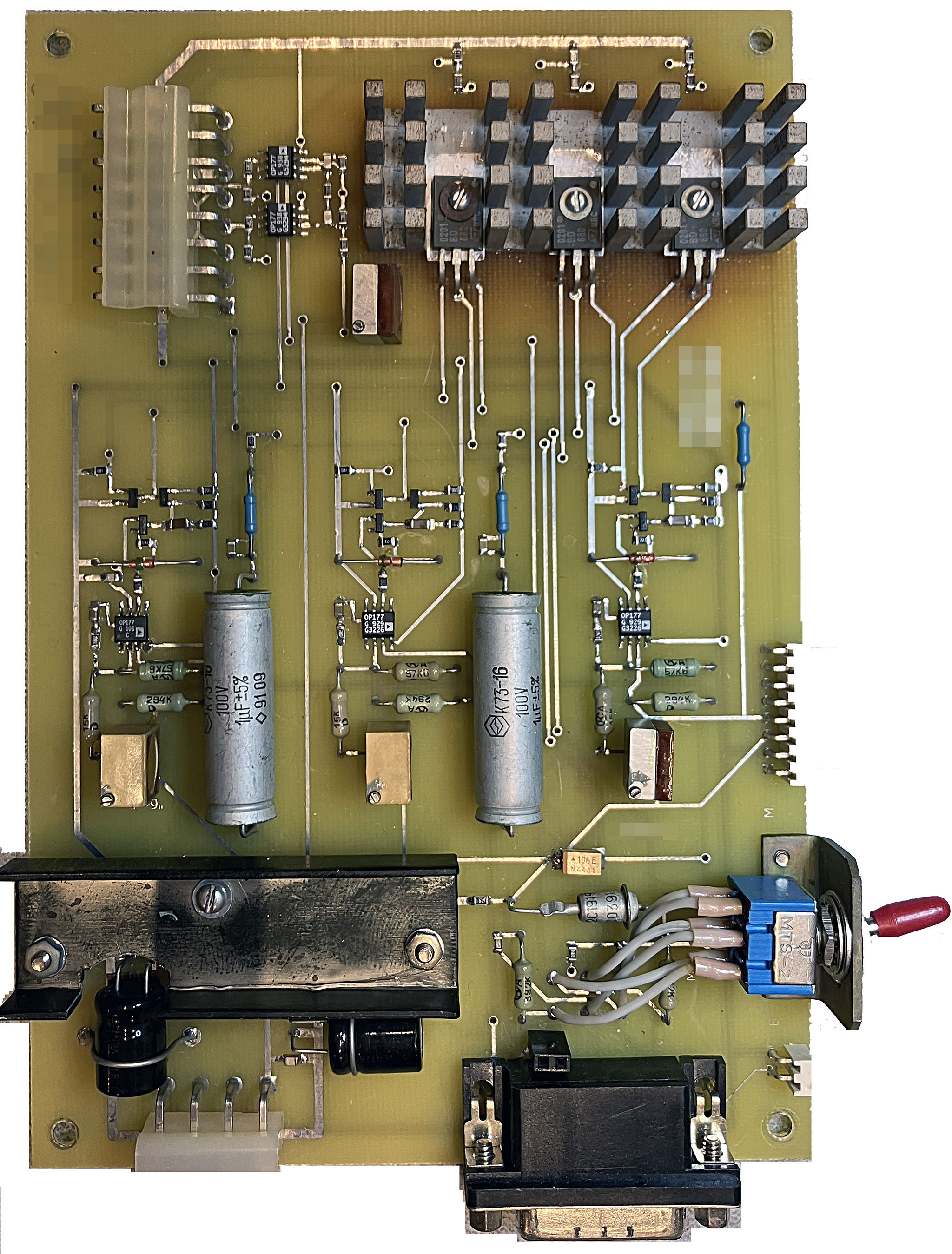
With that, the second picture could be from a spark gap transmitter. Judging by the discoloration around the transistors and their heatsink, it certainly burned a lot of power.
Three transistors mean three channels. The construction of the board suggests something low-ish volume. Very heavy duty housing around the spiral glass tube of some kind. Could it be one light of a traffic light and the controller board for all three lights?
Very interesting hardware indeed, Pink RF transistor, air variable cap and that coil in some kind of RF enclosure, complete with RF gasket. What is that Photodiode doing in there? Some kind of inductively coupled plasma light source? Doesn’t look like atomic clock to me, in terms of frequency and precision.
On the PCB there’s a curious mix of soviet passives and AD opamps and ST transistors. Some kind of linear regulator maybe.
Yeah, it seems like too much RF stuff to be a common traffic light lamp. Another idea: the flat coiled tube is some kind of discharge lamp that is driven at RF frequency to pump a laser.
With very precise feedback-loop controlled brightness ?
I agree with Allen: it is a controller board and single lamp unit for a high-brightness 3-channel filament light. This board appears to have timers associated with relatively high-voltage relay switches, and I assume that you set the hardware’s timing pattern using the serial cable. It could be an older traffic light, or flight control, F1 racing starter, etc. Anyway, it’s a circa 1990s “blinky” lol.
that is a transistor output for what looks like..a fuzz peddle? or a remote controller for a racecar?
I agree that the coil looks a lot like a neon tube, but looking closely I’m thinking it’s just thick wire with maybe a coating for the colour. In series with a piece of coax to form a capacitor and a trimcap, driven by a rather beefy RF looking transistor.
So I’m saying it’s some kind of a power RF source, _maybe_ an inductive RF heater. Whatever it is, it seems to be precisely controlled, because there’s what looks like an IR sensor looking up at where the target would be.
It also has a very prototype-ey look to it. And Russian capacitors at the very least, the other passives have a Russian look to them too. And it comes from a Ham. So very likely RF, maybe a heater, maybe a Soviet Death Ray prototype. Definitely interesting :-)
Some kind of soviet RF aparatus. The pink RF transistor in the first picture is definitely Soviet (KT930?).
The coil is definitely hardline (like UT141). So a series tuned LC circuit, with what looks like a photocell or other optical sensor on the left. Maybe an induction heater with an optical temp sensor?
Given the other materials on the KE5FX website, I am guessing this is part of a rubidium? frequency standard, with the rubidium cavity and lamp missing from the picture. These standards have a photodiode feedback which matches with the photodiode to the left, the coil could be feeding the cavity with microwave energy.
Well, here we are at the end of the month, and I don’t have much of an idea what we’re looking at. I know next to nothing about microwave stuff. I did some of my usual circuit tracing, and got some of the board, including the 3 channels of op amps driving the PNP power transistors at top via the small transistors in between. But it didn’t lead me to any better guesses about what it does. And how the board talks to the RF part is a mystery to me at least.
I’ll toss out a wild guess that it is a line-of-sight microwave link for data or audio. The light sensor is to help with path alignment using a laser or light beam.
This one was posted early :) April’s ware probably won’t go up until near the end of April.