The ware for June 2025 is shown below.
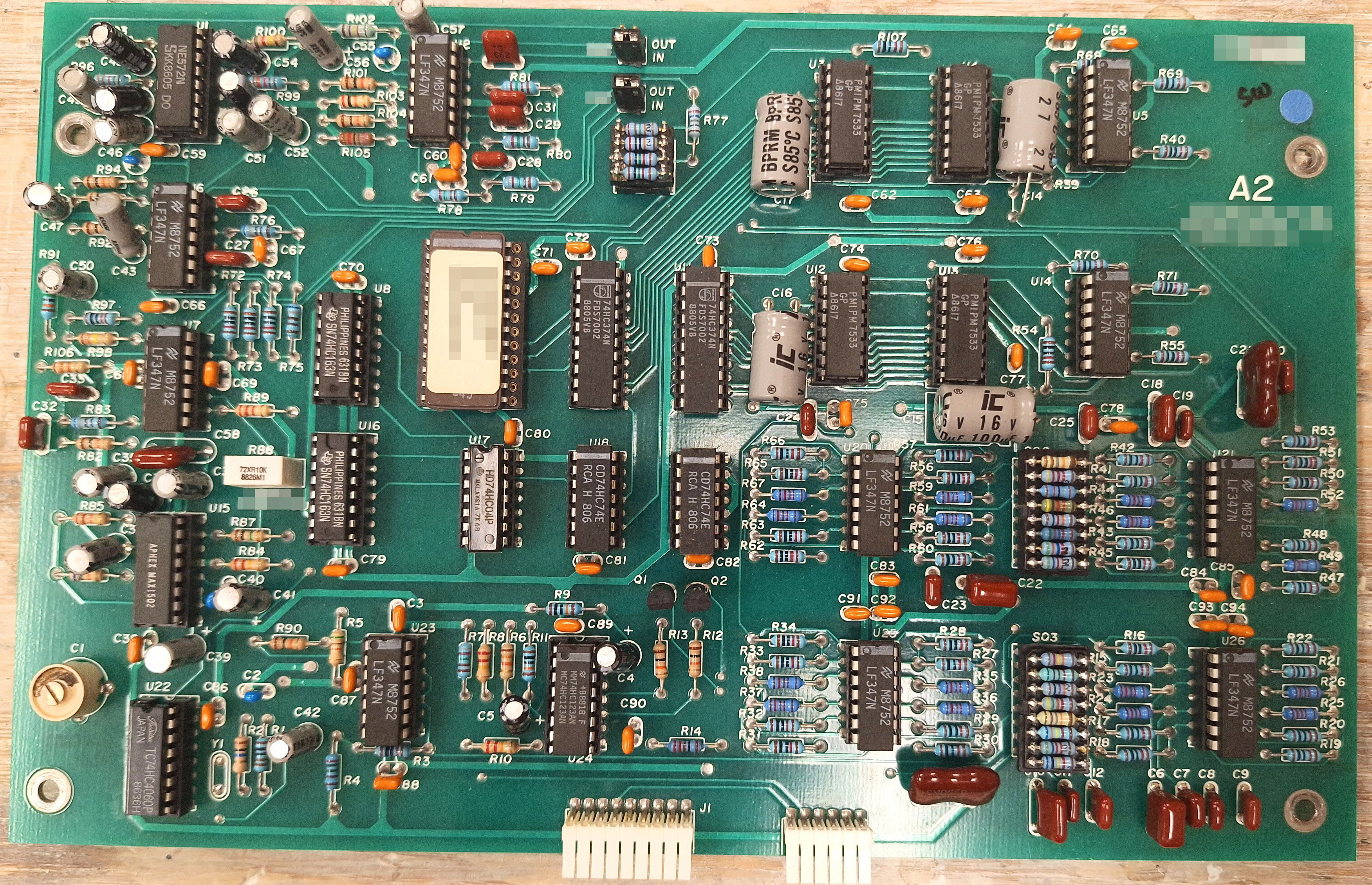
A big thanks to Chris Combs for this handsome contribution! Despite being 80’s vintage, the board is in mint condition.
The ware for June 2025 is shown below.
A big thanks to Chris Combs for this handsome contribution! Despite being 80’s vintage, the board is in mint condition.
From the parts on this board it looks like it could be from one of the phone audio products by Gentner like the EFT-100.
Nice tidy thru hole board!
I see a pair of binary counters driving the fuzzed out DIP which likely feeds the 4 DACs via various logic. Crystal oscillator below the counters. So I’d guess the large DIP ia a PROM and all that forms a waveform generator. The many quad op amps and surrounding parts look like audio processing.
Looking up U15 = Aphex max1502, I found an Aphex manual, not for this board, but listing that part as an “enhancement generator”
Not many I/O’s – looks like +/- Vs and +5V, and a few small traces for signals. No trim pots, that’s cool. But 3 DIP headers with what are likely selected resistors.
So putting those limited observations together, I’m guessing the board is from an audio effects box of some kind made by Aphex. I’ll look at the board more, but that’s what I see at first.
Is this a Dolby Noise Reducer?
My guess is an Aphex Aural Exciter – not gonna pick a particular model right now as my old eyes are struggling to read poorly scanned schematics on my phone ;) but there’s lots of similarities in the choice of chips.
I’ll have a closer look when I have a monitor in front of me.
That weirdly-marked “Aphex Max 1502” IC sent me down a bit of a rabbit hole. Who other than Aphex Systems themselves would use their special-sauce IC? Especially if, as claimed by one random commenter on Facebook, it’s just a remarked NE571? There are lots of online scans of very nicely-drawn schematics that Aphex Systems provided for their equipment, but I couldn’t find anything that matches this board. All of their larger rack-mount equipment seemed to use 3-digit part designators for identifying which board they were on, and the lack of any controls on this PCBA makes it a poor fit for any of their pedals that I could find. None of them had any of the digital stuff on this board either, like the PM7533 DAC.
Eventually, a search for devices containing parts from “Aphex Systems” and the “PM7533” led me to the manual for the Gentner EFT-100. Looks like someone here beat me to it, I’m amazed that you can recognize it just from the component selections! Looking at the schematic page for the “Encode/Decode Card (A2),” it’s a perfect fit, even matching the “A2” silkscreen on this board. All of the component designators (that I could read) match this PCBA, the large EPROM in the middle is an NMC27C16Q-45. I suspect this circuit card was used in multiple different models, since the schematic marks it as part of the EFT-1000.
The manual has an excellent write-up on how this circuit functions, the EPROM is apparently used to generate a “126 sample digital sine and digital cosine wave.” This circuit effectively frequency shifts audio up/down by 250Hz so that low-end audio isn’t lost on analog telephone lines. The Aphex circuit is then used to re-create high-end harmonics when the audio is received, so that it sounds more natural. The manual also includes the lovely warning: “CAUTION! Too much APHEX processing causes severe
distortion.”
Now for some reason I’d really like to listen to some Aphex Twin…
I wake up on the morning of my 67th birthday with a vaguely familiar PCB staring me in the face.
My eyes are eventually drawn to the film capacitors and the header plugs with so many one percent resistors …
MY PAST LIFE IS FLASHING BEFORE MY EYES, I MUST BE GONNA DIE SOON!
Bill Gillman, former VP of Engineering at Gentner and designer of the EFT series, circa 1985.
Nice work :)
Don’t tell me that the header plugs with resistors were hand-binned/matched and that’s why they were on header plugs….I do see some faint hand-written inscriptions tho on some of those resistors, which is “curious” to say the least.
You got it right bunnie. The circuit could be built with 1 percent resistors and make 30 dB of unwanted sideband rejection.
I wanted 40 dB.
The variation unit to unit was due to the film capacitor tolerance of 5%. The normal circuit resistors were increase slightly in value and then trimmed with parallel resistors on the headers. We build a trimming jig that sped up the process. You generated a trim list for manufacturing who then assembled the headers.
So awesome to have you drop by and comment.
Gentner went on to develop the EFT-3000, which was a digital “extended frequency transceiver” system that split a ~7.5kHz audio signal into as many as three ~2.5kHz passbands, each of which was frequency-shifted and passed down a separate telephone line.
The EFT-3000 was based on a pair of Motorola 56K DSPs. The author of the DSP code for that product was a character. One day I, as a fresh college grad, expressed my amazement at the mathematical processing power of those DSPs, which was impressive back in 1989. His response? “That just means you can make 20 million mistakes per second.”