The Ware for February 2021 is shown below.
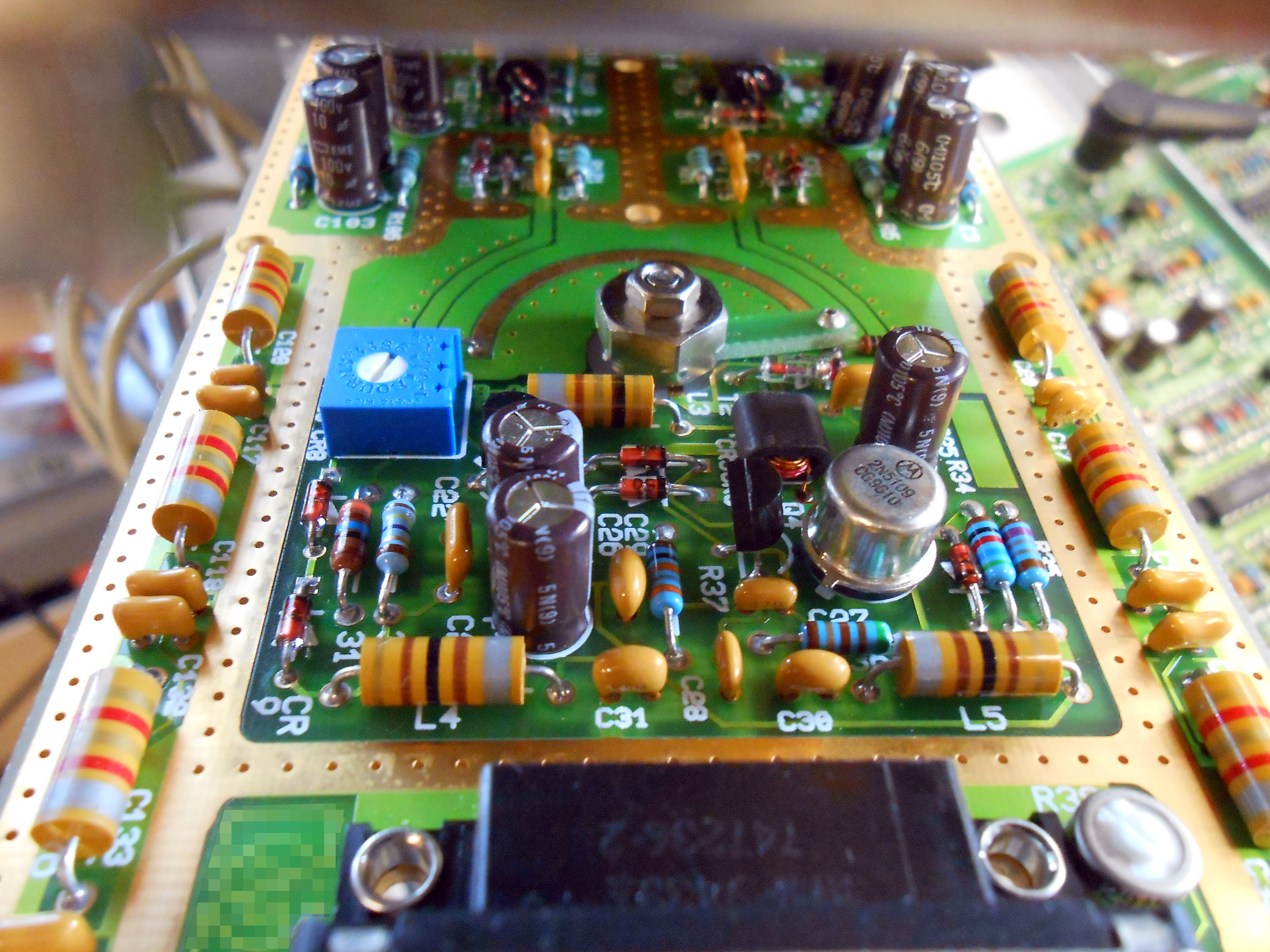
This one’s a bit tougher, since it’s just a small section of the complete circuit board; but I think there’s enough visible to have a stab at what the core function might be of the circuits highlighted here! Should be an interesting stumper.
Thanks again to Don Straney for contributing these wonderful wares!
DB15 looking connector center bottom, Motorola branded metal cap and an otherwise symmetrical circuit. Seems like a wiper and a trimmer pot, too. Intentionally blurred pcb markings just to the right of the connector and all through hole boards out of focus in the background with what looks like an antenna.
Narrow boards and the DB connector have me thinking hand held or possible rack mount or similar. Circuitry has me thinking older radio stuff. If not a handheld remote for some rf calibration or test gear, perhaps one board out of a car phone?
I know absolutely nothing about this, but could this potentially be some sort of stereo audio + rf equipment? It looks like there are symmetrical (potentially filtery) stuff towards the top, and an RF amplifier metal can on the bottom area. I also noticed the wiper and stuff. Honestly I don’t really know what this is.
Thirding the RF, the wiper picking a point along a copper transmission line makes me think a tunable stub matching circuit.
OK I think it’s time for some wild speculation.
That wiper is not resistive, so what does it do? Maybe the two signals coming down are quadrature, and it selects the phase. The bit in front could be a detector of some type. The baluns definitely indicate RF. The size of the components indicate HF not UHF. But it could be the IF of something more gnarly.
So why would one want to do that? Maybe to find the angle your LNB is at, to fine tune the orientation? Or maybe Doppler direction finding? There’s a block diagram here https://www.researchgate.net/profile/Marek-Klemes/publication/331744873/figure/fig6/AS:736441311182857@1552592699809/An-alternative-implementation-of-pseudo-Doppler-OAM-receiving-front-end_Q320.jpg which doesn’t look too dissimilar.
What I can say is I’ve never seen anything like it before.
Could this be used in conjunction w a brinks home monitoring system…but for some other use? Asking for a friend.
I agree with wrm on most counts. This is clearly an RF circuit. The Baluns, the RF transistor (bandwidth product of only 1200Mhz, manufactured in early 1996), the exposed ground with stitching where a custom shield cover can make contact all point to rf in HF (possibly VHF).
Let’s assume that the wiper length is chosen for a reason. One thing it will do is set the phase offset between the two upper paths, at which point the wiper will adjust the phase of the two paths relative to some standard. Quadrature seems reasonable, so let’s assume this arc is 1/4 wavelength.
I am used to seeing this construction on ceramic RF boards (the exposed substrate on the edge also looks a bit like ceramic), which usually have a higher dielectric constant than fr4 (~10 vs ~4). Using the width of the rf transistor I calculate that the board is probably ~75mm wide, which gives us a length for the tunable arc of ~45mm. With a Dielectric of 10, this could be 1/4 wavelength at ~527MHz (error bars are becoming fairly wide at this point). This lands us in the broadcast television range in the US (but I don’t think digital TV that would use quadrature was around in ’96), with a bunch of other uses within our error range, including radio astronomy nearby. This still feels like a high frequency relative to the size of the components, but it is plausible.
Does anyone have ideas for the inductor/capacitor stacks along the edges? I’m thinking those could be filters, possibly we are feeding power into each side through the filters on the edge, in order to clean the relevant frequency off of the power line. I’m thinking that the large connector on the bottom is power and data/control, and there will be a couple of RF coax connectors at the top to feed the two signals to/from other modules.
I did a little more digging and found a similar structure in an article MEMS-based differential beam steering antenna (it was replacing a manual structure such as this one). Assuming this is being used for beam steering I would personally place the total arc length at near one wavelength to allow a full range of steering (possibly less for a limited range and possibly more to allow for tolerances and possibly multiple frequencies in a band). I like this over a quadrature style wiper, because for 1/4 wavelength you are pretty much setting the frequency with the length, but for a beam steering antenna you can accommodate a wider band. Center is straight ahead and it steers left and right with the wiper. If it is more than one wavelength you might start pointing back the opposite way if you go to far, but that isn’t the end of the world.
So assuming this is 1 wavelength that pulls us up to about 2.1GHz. I suppose that could get us up into the ISM band at 2.4-2.5GHz, although the parts look large for such a frequency.
I’ll take a shot and say this is part of a non-destructive testing and inspection system. Some sort of an amplitude phase detector, to process the signal from an inspection probe.
Take a look at the blurred out logo to the left of the connector near the front of the board (closest to the viewer). Look familiar? It’s blurred out, but you, if you squint, you can make out an outlined script ‘hp’.
It’s a modem.