Previously, I had written about developing a reference design for the NeTV2 FPGA using Xilinx’s Vivado toolchain. Last year at 33C3 Tim ‘mithro’ Ansell introduced me to LiteX and at his prompting I decided to give it a chance.
Vivado was empowering because instead of having to code up a complex SoC in Verilog, I could use their pseudo-GUI/TCL interface to create a block diagram that largely automated the task of building the AXI routing fabric. Furthermore, I could access Xilinx’s extensive IP library, which included a very flexible DDR memory controller and a well-vetted PCI-express controller. Because of this level of design automation and available IP, a task that would have taken perhaps months in Verilog alone could be completed in a few days with the help of Vivado.
The downsides of Vivado are that it’s not open source (free to download, but not free to modify), and that it’s not terribly efficient or speedy. Aside from the ideological objections to the closed-source nature of Vivado, there are some real, pragmatic impacts from the lack of source access. At a high level, Xilinx makes money selling FPGAs – silicon chips. However, to attract design wins they must provide design tools and an IP ecosystem. The development of this software is directly subsidized by the sale of chips.
This creates an interesting conflict of interest when it comes to the efficiency of the tools – that is, how good they are at optimizing designs to consume the least amount of silicon possible. Spending money to create area-efficient tools reduces revenue, as it would encourage customers to buy cheaper silicon.
As a result, the Vivado tool is pretty bad at optimizing designs for area. For example, the PCI express core – while extremely configurable and well-vetted – has no way to turn off the AXI slave bridge, even if you’re not using the interface. Even with the inputs unconnected or tied to ground, the logic optimizer won’t remove the unused gates. Unfortunately, this piece of dead logic consumes around 20% of my target FPGA’s capacity. I could only reclaim that space by hand-editing the machine-generated VHDL to comment out the slave bridge. It’s a simple enough thing to do, and it had no negative effects on the core’s functionality. But Xilinx has no incentive to add a GUI switch to disable the logic, because the extra gates encourage you to “upgrade” by one FPGA size if your design uses a PCI express core. Similarly, the DDR3 memory core devotes 70% of its substantial footprint to a “calibration” block. Calibration typically runs just once at boot, so the logic is idle during normal operation. With an FPGA, the smart thing to do would be to run the calibration, store the values, and then jam the pre-measured values into the application design, thus eliminating the overhead of the calibration block. However, I couldn’t implement this optimization since the DDR3 block is provided as an opaque netlist. Finally, the AXI fabric automation – while magical – scales poorly with the number of ports. In my most recent benchmark design done with Vivado, 50% of the chip is devoted to the routing fabric, 25% to the DDR3 block, and the remainder to my actual application logic.
Tim mentioned that he thought the same design when using LiteX would fit in a much smaller FPGA. He has been using LiteX to generate the FPGA “gateware” (bitstreams) to support his HDMI2USB video processing pipelines on various platforms, ranging from the Numato-Opsis to the Atlys, and he even started a port for the NeTV2. Intrigued, I decided to port one of my Vivado designs to LiteX so that I could do an apples-to-apples comparison of the two design flows.
LiteX is a soft-fork of Migen/MiSoC – a python-based framework for managing hardware IP and auto-generating HDL. The IP blocks within LiteX are completely open source, and so can be targeted across multiple FPGA architectures. However, for low-level synthesis, place & route, and bitstream generation, it still relies upon proprietary chip-specific vendor tools, such as Vivado when targeting Artix FPGAs. It’s a little bit like an open source C compiler that spits out assembly, so it still requires vendor-specific assemblers, linkers, and binutils. While it may seem backward to open the compiler before the assembler, remember that for software, an assembler’s scope of work is simple — primarily within well-defined 32-bit or so opcodes. However, for FPGAs, the “assembler” (place and route tool) has the job of figuring out where to place single-bit primitives within an “opcode” that’s effectively several million bits long, with potential cross-dependencies between every bit. The abstraction layers, while parallel, aren’t directly comparable.
Let me preface my experience with the statement that I have a love-hate relationship with Python. I’ve used Python a few times for “recreational” projects and small tools, and for driving bits of automation frameworks. But I’ve found Python to be terribly frustrating. If you can use their frameworks from the ground-up, it’s intuitive, fun, even empowering. But if your application isn’t naturally “Pythonic”, woe to you. And I have a lot of needs for bit-banging, manipulating binary files, or grappling with low-level hardware registers, activities that are decidedly not Pythonic. I also spend a lot of time fighting with the “cuteness” of the Python type system and syntax: I’m more of a Rust person. I like strictly typed languages. I am not fond of novelties like using “-1” as the last-element array index and overloading the heck out of binary operators using magic methods.


Surprisingly, I was able to get LiteX up and running within a day. This is thanks in large part to Tim’s effort to create a really comprehensive bootstrapping script that checks out the git repo, all of the submodules (thank you!), and manages your build environment. It just worked; the only bump I encountered was a bit of inconsistent documentation on installing the Xilinx toolchain (for Artix builds you need to grab Vivado; and Spartan you grab ISE). The whole thing ate about 19GiB of hard drive space, of which 18GiB is the Vivado toolchain.
I was rewarded with a surprisingly powerful and mature framework for defining SoCs. Thanks to the extensive work of the MiSoC and LiteX crowd, there’s already IP cores for DRAM, PCI express, ethernet, video, a softcore CPU (your choice of or1k or lm32) and more. To be fair, I haven’t been able to load these on real hardware and validate their spec-compliance or functionality, but they seem to compile down to the right primitives so they’ve got the right shape and size. Instead of AXI, they’re using Wishbone for their fabric. It’s not clear to me yet how bandwidth-efficient the MiSoC fabric generator is, but the fact that it’s already in use to route 4x HDMI connections to DRAM on the Numato-Opsis would indicate that it’s got enough horsepower for my application (which only requires 3x HDMI connections).
As a high-level framework, it’s pretty magical. Large IP instances and corresponding bus ports are allocated on-demand, based on a very high level description in Python. I feel a bit like a toddler who has been handed a loaded gun with the safety off. I’m praying the underlying layers are making sane inferences. But, at least in the case of LiteX, if I don’t agree with the decisions, it’s open source enough that I could try to fix things, assuming I have the time and gumption to do so.
For my tool flow comparison, I implemented a simple 2x HDMI-in to DDR3 to 1x HDMI-out design in both Vivado and in LiteX. Creating the designs is about the same effort on both flows – once you have the basic IP blocks, instantiating bus fabric and allocation of addressing is largely automated in each case. Vivado is superior for pin/package layout thanks to its graphical planning tool (I find an illustration of the package layout to be much more intuitive than a textual list of ball-grid coordinates), and LiteX is a bit faster for design creation despite the usual frustrations I have with Python (up to the reader’s bias to decide whether it’s just that I have a different way of seeing things or if my intellect is insufficient to fully appreciate the goodness that is Python).
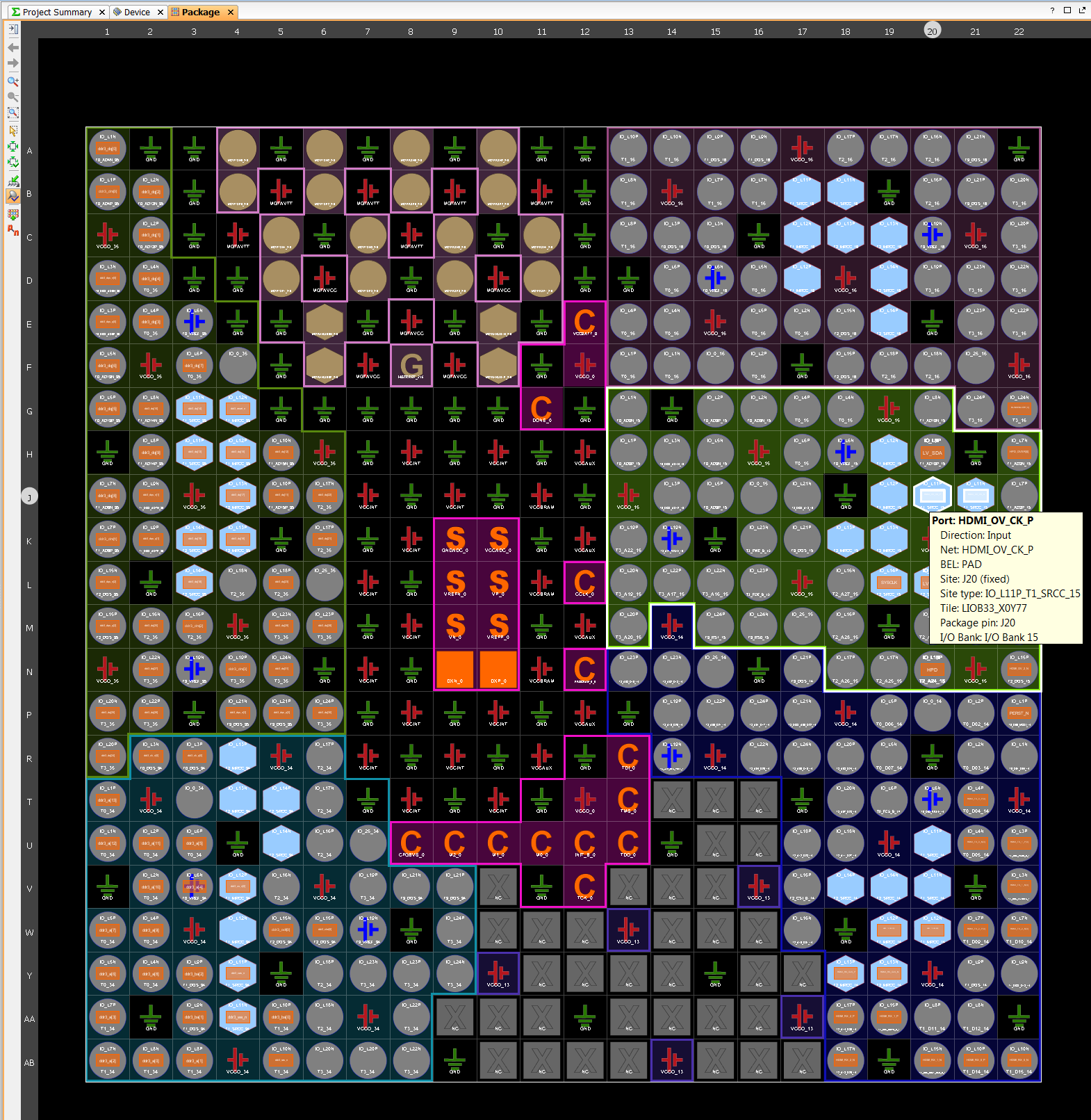
Pad layout planning in Vivado is aided by a GUI
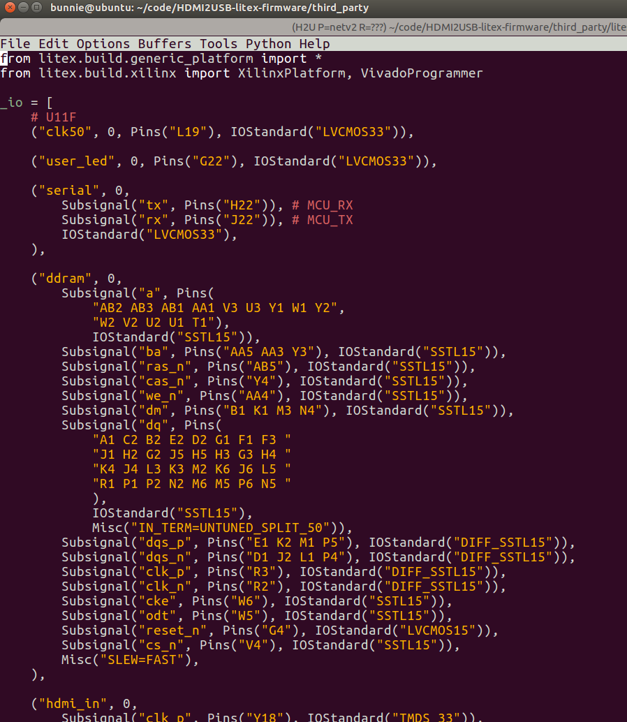
Example of LiteX syntax for pin constraints
But from there, the experience between the two diverges rapidly. The main thing that’s got me excited about LiteX is the speed and efficiency of its high-level synthesis. LiteX produces a design that uses about 20% of an XC7A50 FPGA with a runtime of about 10 minutes, whereas Vivado produces a design that consumes 85% of the same FPGA with a runtime of about 30-45 minutes.
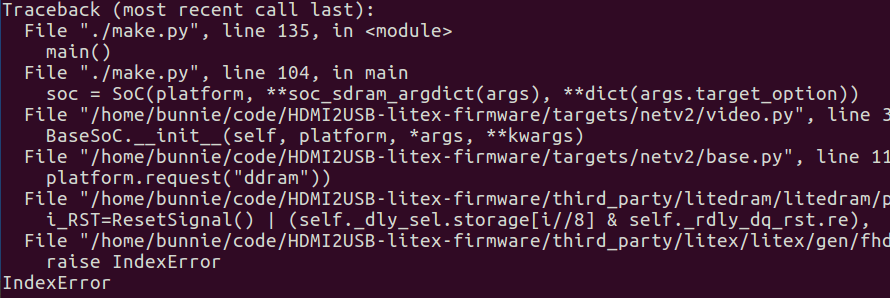
Significantly, LiteX tends to “fail fast”, so syntax errors or small problems with configurations become obvious within a few seconds, if not a couple minutes. However, Vivado tends to “fail late” – a small configuration problem may not pop up until about 20 minutes into the run, due to the clumsy way it manages out-of-context block synthesis and build dependencies. This means that despite my frustrations with the Python syntax, the penalty paid for small errors is much less in terms of time – so overall, I’m more productive.
But the really compelling point is the efficiency. The fact that LiteX generates more efficient HDL means I can potentially shave a significant amount of cost out of a design by going to a smaller FPGA. Remember, both LiteX and Vivado use the same back-end for low-level sythesis and place and route. The difference is entirely in the high-level design automation – and this is a level that I can see being a good match for a Python-based framework. You’re not really designing hardware with Python (eventually it all turns into Verilog) so much as managing and configuring libraries of IP, something that Python is quite well suited for. To wit, I dug around in the MiSoC libraries a bit and there seem to be some serious logic designs using this Python syntax. I’m not sure I want to wrap my head around this coding style, but the good news is I can still write my leaf cells in Verilog and call them from the high-level Python integration framework.
So, I’m cautiously proceeding to use LiteX as the main design flow going forward for NeTV2. We’ll see how the bitstream proves out in terms of timing and functionality once my next generation hardware is available, but I’m optimistic. I have a few concerns about how debugging will work – I’ve found the Xilinx ILA cores to be extremely powerful tools and the ability to automatically reverse engineer any complex design into a schematic (a feature built into Vivado) helps immensely with finding timing and logic bugs. But with a built-in soft CPU core, the “LiteScope” logic analyzer (with sigrok support coming soon), and fast build times, I have a feeling there is ample opportunity to develop new, perhaps even more powerful methods within LiteX to track down tricky bugs.
My final thought is that LiteX, in its current state, is probably best suited for people trained to write software who want to design hardware, rather than for people classically trained in circuit design who want a tool upgrade. The design idioms and intuitions built into LiteX pulls strongly from the practices of software designers, which means a lot of “obvious” things are left undocumented that will throw outsiders (e.g. hardware designers like me) for a loop. There’s no question about the power and utility of the design flow – so, as the toolchain matures and documentation improves I’m optimistic that this could become a popular design flow for hardware projects of all magnitudes.
Interested? Tim has suggested the following links for further reading:
- Getting started with LiteX
- Tim ‘mithro’ Ansell’s talk at Linux.conf.au 2017 about why he finds LiteX / MiSoC so powerful.
- Migen Manual
- Tim ‘mithro’ Ansell (and friends) are running a day long tutorial on using LiteX and Linux together at Linux.conf.au 2018 – If you are in Australia, I recommend checking it out. I’ll be speaking at the full conference too!
- Cr1901’s tutorial for adding a new FPGA board to Migen
- M-Lab’s the creators of Migen + MiSoC & Enjoy Digital, creators of LiteX and the other Lite cores
- Implementing a simple SoC using Migen and Project IceStorm (the fully open source FPGA toolchain for the Ice40)