Archive for the ‘Hacking’ Category

Name that Ware October 2009

Wednesday, October 7th, 2009

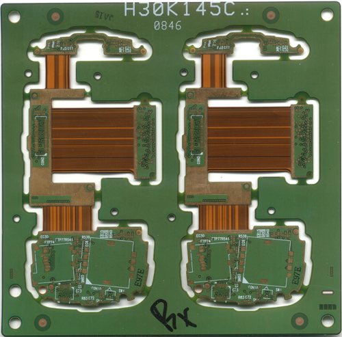
The Ware for this month is shown below. Click on the image for a much larger version.

This ware is a simple circuit board — again one that I just randomly grabbed in the Shenzhen gray markets, so I actually don’t know what phone it’s from. It should be interesting to find out based on people’s guesses. I’m sharing this one with you primarily because it’s a great example of a flex-rigid circuit board construction. In this design, four PCBs are joined together with an embedded laminate flex cable. The flex cable is sandwiched right in the middle of the PCB stack with no connectors or soldering: just the native PCB vias establish connectivity to the cables. This saves on board area and improves signal integrity. It’s a really cool technology and I wish it was a little bit cheaper and more accessible to hobbyists — it can find a lot of uses in tight spots such as those in UAVs, robots, and other mobile devices.

Things are running a little crazy this month with the release of the chumby one coming up. Been wanting to blog about designing and building this one, but I’ve had to save it up until after the device is launched… And, as usual, schematics will be shared for the device. This should be a fun one for the hackers because of its lower price (less anxiety over breaking it), microSD based firmware (no need for a ROM burner or worrying about bricking the device when hacking it, and it uses ext3 instead of cramfs so you can easily remount the rootfs read-write), and the fact that it’s screwed together instead of glued together.

Winner, Name that Ware September 2009

Wednesday, October 7th, 2009

The Ware for September 2009 is an HP5061A cesium beam frequency standard, upgraded with 5061B components and a third-party replacement tube from Datum. Thanks to KE5FX for the ware submission!

As suspected, it was almost entirely guessed the moment it went up. However, I’d have to say overall Brian had the most accurate guess of all. Congrats brian, email me to claim your prize!

And here’s a photo of the ware without all the naughty bits covered up:

Tenori-On Teardown

Sunday, September 13th, 2009

Joi Ito brought a neat toy to FOO Camp this year — a Tenori-On. The Tenori-On is this very interactive, beautiful piece of hardware created by Toshio Iwai that, to paraphrase his words, creates a “visible music” interface with a shape and sound that fits the player organically, a sort of re-invention of the violin for the digital age. Here’s a neat YouTube demo of the Tenori-On. I had seen this instrument for the first time in a fabulous live performance by Cornelius in Tokyo, and had since lusted for it.

Joi was an amazingly good sport, and let me do what I instinctively want to do when I see a piece of sexy hardware like this — undress it! Thankfully, I always travel with screwdrivers and a camera to capture rare opportunities like this, so I was able to capitalize on the moment. I did get it apart (and put back together again!!), and here are some photos of the innards to share with you. I’ll eventually throw these photos up on ifixit, it’s a better site for sharing teardowns.

(Most images click to reveal a larger version)

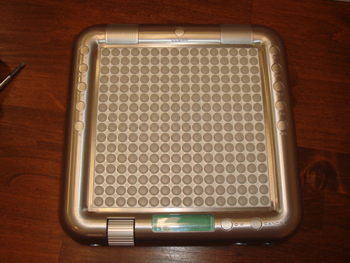
Such a pretty face.

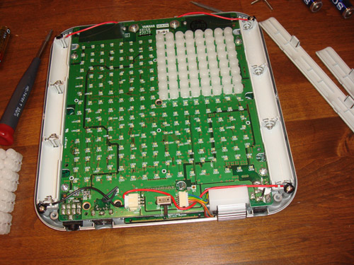
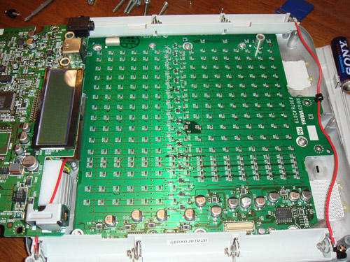
Backside view, showing the array of 256 decorative LEDs on the backside. The button sheets are, in this case, dummies used to diffuse the LED light evenly.

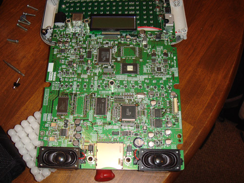
The brains of the Tenori-On. Nice piece of work, well laid out (very nice symmetry around all the parts, good isolation of analog and digital), some premium component choices.

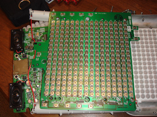
Backside of the 256-switch + LED array. There’s a diode at each intersection of the keyboard scan array.

Front side of the 256-switch + LED array that’s behind the active button panel.

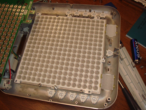
The backside of the front bezel, showing the array of buttons. The case is made out of cast Aluminum, which is a pretty expensive technology for a relatively low-run product. Each button is carefully designed to allow for a uniform spreading of the LED light while also allowing for easy pressing of the offset switch.

Thanks again to Joi for letting me open up this baby!

Name That Ware, September 2009

Wednesday, September 9th, 2009

The Ware for September 2009 is shown below. Click on the image for a slightly larger version.

This Ware is again a user-submitted ware. I have a sneaking suspicion that someone out there will guess this one fairly quickly, even though all the naughty bits are obscured in the photo, but I think it’s a neat one because I’ve never seen the insides of one of these before myself.

Winner, Name that Ware August 2009

Wednesday, September 9th, 2009

The Ware for August 2009 is the Viking Lander Command Detector Board (VCLD). The Viking Landers were robotic probes sent to Mars in the 1970’s. The board itself dates from 1970.

The Ware was submitted by Norman Yarvin, and fortunately, the original author of the report on the circuit board, Bob Schuster, was in the loop to explain what it did, and how it was made.

Some notes from Bob Schuster:

  • The big round thing in the lower right hand corner was an xtal used in the bit timing oscillator.
  • The larger empty rectangular space on the lower left was for a voltage controlled xtal oscillator used in the subcarrier recovery circuits.
  • Most of the components used were already 5 or more years in vintage, there were “better” parts, but we were using only established reliability parts.
  • A very detailed, and quite interesting, report summary was written by Bob, that explains the design approach behind the board and how it worked. Here’s an excerpt:

    This board is one of two boards (primary & redundant) and was part of the Command Control Unit (CCU) a box that also contained power supplies and antenna control electronics-plus other stuff which I forget. It was flown on the Viking mission to Mars and was the first USA landing of a spacecraft on another planet. Its mission was imaging and the search for evidence of life.

    NASA’s web site should be visited for more information about Viking.

    Since its mission included a search for evidence of life all flight hardware on the Lander had to be sterilized in an oven at 254 degrees F (123deg C) for two days before it could be launched. It still had to function after the sterilization of course.

    The board shown in the picture is the first Engineering Test Model (ETM) produced and that is why there are so many cuts and jumpers visible. The dust evident in the pictures (not very sterile) is from sitting around my attic these many years. I should have made it prettier but this was done on the spur of the moment.

    The purpose of the board was to recover –- reliably — the digital data being up-linked to the Lander computer from earth. The computer could then be re-programmed as conditions changed or as mission scientist came up with new things to try. The emphasis on reliability was due to the low bit rate viz 4bits/sec and the limited time available each earth day to send reprogramming commands plus the long transit times for the radio signals to reach Mars (maybe about 3 to 4 sun earth transit times or about 4x9min=36 minutes ONE WAY. If the computer data had more than one error it could not correct it, or if the detector declared a poor subcarrier signal or bad bit timing the Lander was programmed to request a retransmission of the data from earth. This event triples the time to get data uploaded to about 1.8 hours! A bit error rate of 1bit in every 100000 bits was selected by systems engineering as an error rate the mission could live with. This would presumably keep code retransmission to a minimum thereby not burning up precious contact time. Given the available transmission power of the Goldstone Tracking station and the vast distances involved the S/N ratio was just sufficient to get to the error rate specified. If the error rate was not achieved then retransmissions episodes would get too numerous and the mission would be compromised. So the VLCD had to make maximium use of the available S/N and not degrade the signal in the data recovery process.

    It’s amazing this was done in the early 70’s — years before PCs were introduced — and it’s advanced communications research similar to this that laid the foundations of the mobile phone networks that we take for granted today.

    You can read the full summary report here (small — 40 kB). For those interested in the original history, I also have a PDF of some scans of the original pages (large — 3 MB) of the report typed up in 1971.

    Oh, and the winner — a bit hard to pick since there were a lot of thoughtful comments; I’ll go with Wang-Lo. Even though I’m not quite sure the coax cables were used as part of a delay line differentiator, he did posit a guess that this was for the Viking spacecraft. Congrats, email me for your prize.