The Factory Floor, Part 3 of 4:
Industrial Design for Startups
Sex sells. The performance of a CPU or amount of RAM in a box, to within a factor of two or so, is less important to a typical consumer than how the device looks. Apple devices command a hefty premium in part because of their slick industrial design, and many product designers aim to emulate the success of Sir Jony Ives in their own products.
There are many schools of thought in industrial design. One school invokes the monastic designer, coming up with a beautiful, pure concept, and the only thing the production engineers can do is spoil the purity of the design. Another school invokes the pragmatist designer, working closely with the production engineers, hammering out gritty compromises to produce an inexpensive and high-yielding design.
In my experience, neither extreme is compelling. The monastic approach often results in an unmanufacturable product that is either late to market or exorbitant to produce. The pragmatist approach often results in in a cheap look and feel, to which consumers have trouble assigning a significant value. The real trick is understanding how to strike a balance between the two.
Trim and finish are difficult, and therefore a point of distinction when it comes to design. The current design fad is minimalism, with an emphasis on “honest” finishes. An honest finish features the natural properties of the material systems in play, and eschews the use of paints and decals. Minimalist, honest designs are very hard to manufacture. Minimal designs have…well, minimal, features – and as a result even tiny blemishes stand out. Honest finishes likewise can be very difficult, as an honest finish means no paint: all the burs, gates, sinks, knits, scoring and flow lines that are a fact of life in manufacturing are laid naked before the consumer. As a result, this school of design requires well-made tools that are constantly checked and maintained throughout production.
If you don’t have pockets deep enough to invest in new equipment and capabilities on behalf of your factory (i.e., if you’re not a Fortune 500 company), the first step is to learn the vocabulary available. A design vocabulary is defined by the capabilities of the factory or factories producing the goods. What materials, what finish, what tolerances are achievable, what fastening technology is available – these are all heavily dependent upon the processes available.
Therefore, I find that visiting a factory in person early in the design process results in a better design result. In a factory visit, some design vocabulary will be discarded, but some new vocabulary will be discovered as well – the engineers who work the factory day in and day out develop process innovations that can open up novel design possibilities that are not knowable without the on-site visit.
The chumby One contains a concrete example of the impact manufacturing process can have on design outcome. In the original concept art, the blue highlight around the front edge was added to evoke the feeling of a speech balloon, like those used in captioning comics – the idea being the chumby is captioning your world with snippets from the Internet.
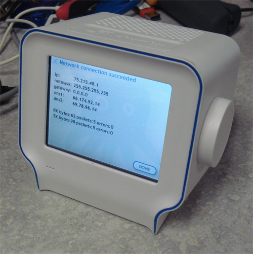
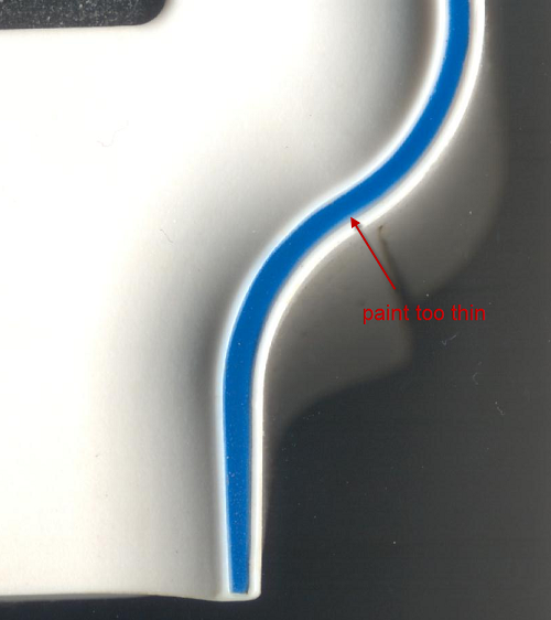
It turns out the implementation of such a blue trim across a raised surface is very hard. At the first factory, we implemented the highlight using paint. Silk screening was not an option because the shape wasn’t flat enough. Pad printing can handle curved surfaces, but the alignment wasn’t good enough, as the tiniest bleed over the edge looked terrible from the side. Decals and stickers likewise could not achieve the alignment required. In the end, a small channel had to be carved to contain the paint, and a stencil plus spray paint process was employed to create the highlight. The yield was terrible – in some lots, over 40% of the cases were being thrown away due to painting errors. Fortunately, plastic is cheap, so throwing away every other case after painting had a net cost impact of about $0.35.
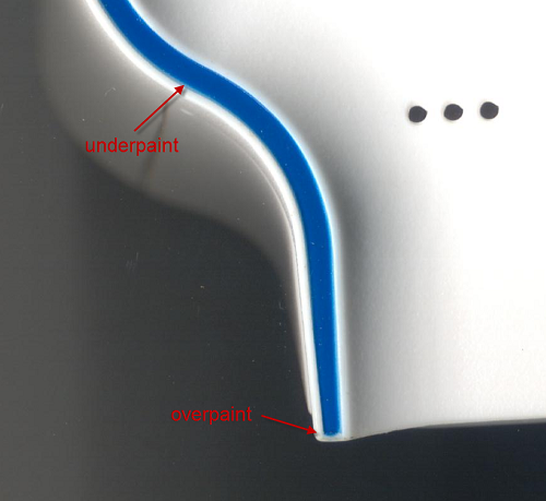
Mid-way through production, we migrated to a second source facility. They had a different plastic molding capability, and unlike the first factory, the second facility could do double-shot molds. Double-shot molds have twice the number of tools, but they can injection mold two different colors, or even different materials, into the same mold. Thus, at the new factory, we opted to use a double-shot process for the thin blue strip, instead of painting. The results were stunning. Every unit came off the line with a sharp, crisp blue line; and no paint meant a more honest, clean finish. However, the cost per case jumped to $0.94 a piece due to the more expensive process, despite the 100% yield. In fact, it would be cheaper to throw away more than half of the painted cases, but even the best painted cases could not compare to the quality of the finish delivered by the double-shot tool.

Another great example of how tweaking a factory process can improve a product’s appearance is the Arduino motherboard. The wonderfully detailed artwork on the back side, sporting an outline of Italy and very fine lettering, isn’t silkscreen. They actually put on two layers of soldermask, one blue, and one white. Because soldermask is applied using a photolithographic process, the resolution, consistency and alignment of the artwork is much better than a silkscreen. And since an Arduino’s look is the circuit board, it gives the product a distinctive high-quality look that is difficult to copy using conventional processing methods.

Thus, the process capability of the factory – painting vs. double-shot molding, double soldermasking vs. silkscreening – can have a real effect in the outcome of a product’s perceived quality, without a huge impact on cost. However, a factory may not appreciate the full potential of their processes, and so it requires a designer’s direct interaction to realize the potential. Unfortunately, many designers don’t visit a factory until something has gone wrong, at which point the tools are cut and even if they see a cool process that could solve all their problems, it’s often too late.
Design is an intensely personal activity, and as a result every designer will develop their own process. This is the general process I might use to develop a product on a tight, startup budget:
-
1. Every design starts with a sketchbook. First, decide on the soul and identity of the design, and pick a material system and vocabulary that suits your concept. But don’t fall in love with it…
2. Break the design down by material system, and identify a factory capable of producing each material system.
3. Visit the facility, and take note of what is actually running down the production lines. Don’t get too drawn in by the sample room or one-off bits. Practice makes perfect, and from the operators to the engineers they will do a better job of executing things they are doing on a daily basis than reaching deep and exercising an arcane capability.
4. Re-evaluate the design based on a new understanding of what’s possible, and iterate. This may require going back to step 1, or it may just require small tweaks. But this is the stage at which it’s easiest to make compromises without sacrificing the purity of the design.
5. Rough out the details of the design – pick parting lines, sliding surfaces, finishes, fastening systems, etc. based upon what the factory can do best.
6. Pass a revised drawing to the factory, and work with them to finalize details such as draft angles, fastening surfaces, internal ribbing, etc.
7. Validate the design using a 3D print and extensive 3D model checks.
8. Identify features prone to tolerance errors, and trim the initial tool so that the tolerance favors “tool-safe” modifications. For example, in injection molding it is easier to remove steel than to add it to a tool, so target the initial test shot to have less plastic than too much on critical dimensions. A button is an example of a mechanism that benefits from tuning: it’s hard to predict from CAD or 3D prints exactly how a button will feel, and getting that tactile feel just perfect usually requires a little trimming of the tool.
Hi –
I’m wondering what/ how you found the vendor for the double shot.
We’ve been using Alibaba – but found we keep getting these Sourcing companies that then turn around and find some low quality vendor.
We want to get in direct contact with a good vendor who can do double shot – over mold rubber over silicone.
Even the contact of your vendors would helpful.
And pointers would be great help.
Thanks in Advance.
[…] starts with part of a blog post series I did a while back, “The Factory Floor, Part 3 of 4: Industrial Design for Startups”. In that post, I outline a methodology for factory-aware design, and I applied these methods when […]
Hi everybody :) I’m rather new to 3d printing and I have many questions on the subject, so I hope you will not get mad at me for asking here at least couple of them. I think before I’ll get seriously into designing I should focus on the software itself, and that’s what I’d like to ask you about. Mainly, should I start with the most simple CAD there is or would it be better to start on something more complicated? I’m worried that I’ll get some undesirable quirks while working with less complex software. Second question is about the program as well: should I search for software that will let me design and slice it in it, or should I use a different software for each of them? Will it even make a difference? Weirdly, I couldn’t find the answer to that, as it seems like most blogs and sites want to focus on the very basics (like what is 3d printing and so on), and while the answers to those questions are fine, it seems like no one wants to go into the details (it looks like some of them even steal from each other! I swear I’ve read the same answers to the same questions on at least 3 different articles) but I’m getting off-topic… The last question is about 3d pens. Would it be possible to somehow convert whatever I draw with a 3d pen to a 3d model in a CAD software? For example, if I’ll draw a cat with 3d pen, would it be possible to get its design in a software? I’m not sure how that could even work, but the very idea sounds interesting to me. Anyway, I think I’ll stop here just in case no one will answer me and all of this writing will go to waste. I’m sorry that I’m using your content to ask questions, but I hope you can relate and help a newbie like me. Anyway, thank you for posting. I learned something from this and that’s always appreciated. Thank you, and I hope to hear back from you very soon :)